The Terrain Analysis Engine provides classes to compute the line-of-sight between two points and between a point and its environment. Both direct and radar line-of-sight computations are supported. Due to radar wave properties a radar can look over a hill.
LOS calculations without OpenCL hardware acceleration
This section discusses how to compute line-of-sight without using OpenCL hardware acceleration. There are two core functionalities:
line-of-sight between two points and between point and its environment. Both functionalities are demonstrated in the example
samples.tea.gxy.los.MainPanel.
LOS calculation from point to environment
Coverage
The Terrain Analysis Engine provides the functionality to compute a line-of-sight from a center point to its surrounding area.
Assuming that the maximum range of visibility is the same in every direction, the area is defined as a circular or polar coverage.
This type of area is represented by the class ILcdLOSCoverage. It contains the following properties, they are clarified in Figure 1, “The properties of a line-of-sight coverage.”:
-
centerPoint: The point around which the area is covered.
-
centerPointReference: The reference in which the center point is defined.
-
centerPointAltitude: The altitude of the center point.
-
centerPointAltitudeMode: The altitude mode indicating how to interpret the center point altitude. Should the height be interpreted as above object (relative to centerPoint), as above ground (relative to terrain data), as above ellipsoid (relative to centerPointReference) or as above geoid (relative to centerPointReference)?
-
radiusMax: The radial extent of the coverage area.
-
radiusStep: The radial discretization step used to find the computation points.
-
angleStart: The starting angle of the arc which defines the coverage area.
-
angleArc: The angular extent of the arc which defines the coverage area.
-
angleStep: The angular discretization step used to find the computation points.

Propagation functions
Next to the coverage area, a propagation function is required in order to compute the line-of-sight. A propagation function,
represented by the interface ILcdLOSPropagationFunction, will calculate the line-of-sight along a given azimuth and it will store the result in a polar matrix. This matrix is represented
by the interface ILcdPolarMatrixView. The Terrain Analysis Engine provides three implementations of the line-of-sight propagation function interface:
-
TLcdLOSRadarPropagationFunction: computes the minimal height for which an object is visible from the center point. The result corresponds to the green line in Figure 2, “The radar propagation result.”. The two dotted lines represent the visible area for the pilot in the helicopter.
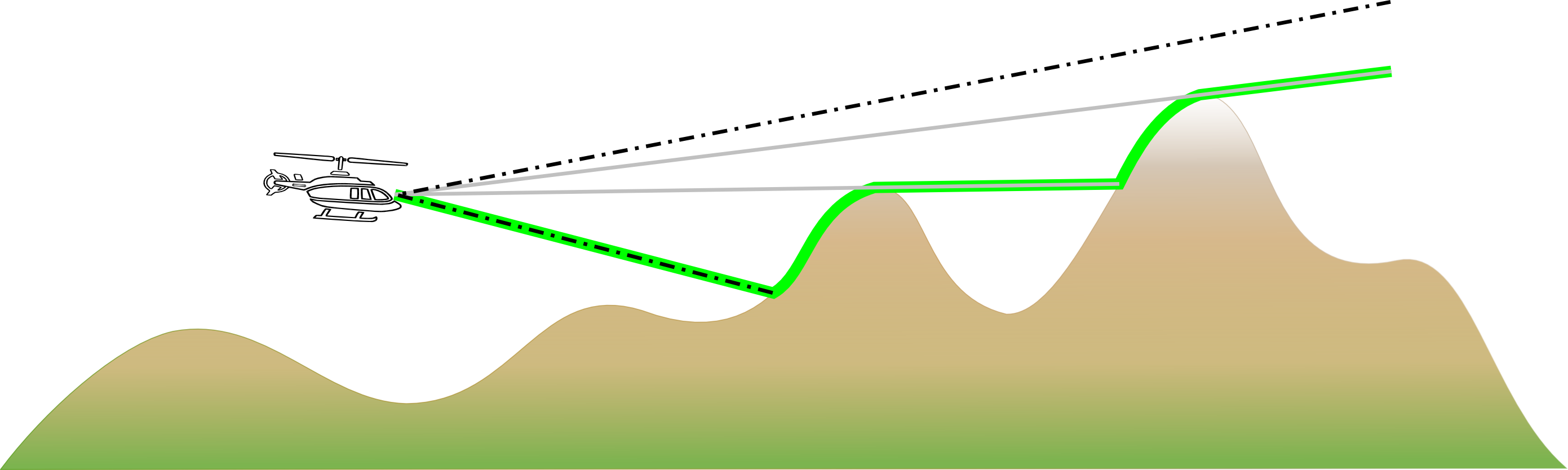 Figure 2. The radar propagation result.
 -
TLcdLOSRadarPropagationFunctionSkyBackground: computes the minimal height for which an object is visible from the center point with the sky as background. This corresponds to the green line in Figure 3, “The sky in background propagation result.”. The thin black line represents a previous line-of-sight computation, required by this function.
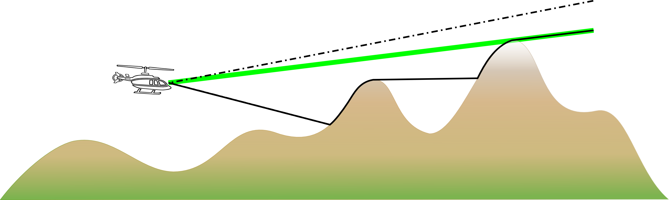 Figure 3. The sky in background propagation result.
 -
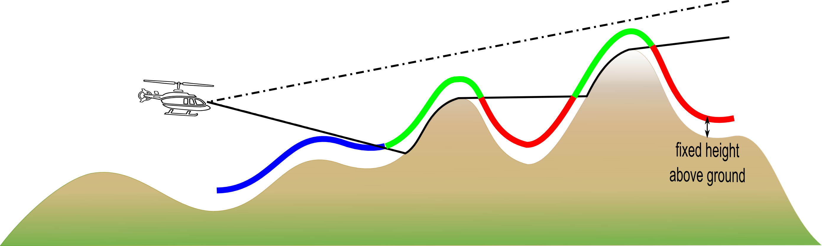
TLcdLOSPropagationFunctionFixedHeight: computes the visibility of an object at a fixed height from a given point. It returns three values as seen in Figure 4, “The propagation result with an above ellipsoid fixed height.” and Figure 5, “The propagation result with an above ground fixed height.”. The green line corresponds to points where the object is visible. The red line corresponds to invisible points due to the obstruction of the terrain, while the blue line corresponds to invisible points due to the cone of silence around the given point. The cone of silence is a cone-shaped region, directly above and below the center point, in which nothing is detected. The thin black line represents a previous line-of-sight computation, required by this function.
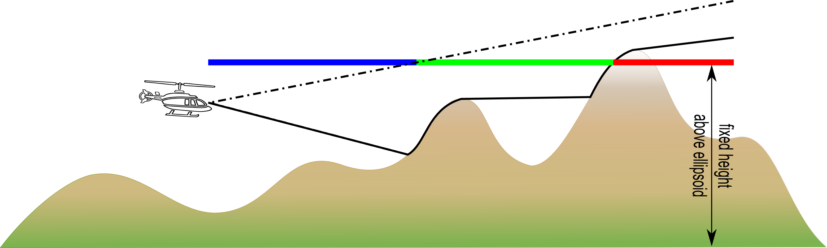 Figure 4. The propagation result with an above ellipsoid fixed height.
The radar implementation (TLcdLOSRadarPropagationFunction) is the main class for computing a line-of-sight. In order to compute a line-of-sight, the function needs to know how to
model the surface of the earth. Currently, two earth representation modes are supported:
-
TLcdEarthRepresentationMode.SPHERICAL_FIXED_RADIUS: which models the earth as a sphere with a radius ofTLcdConstant.EARTH_RADIUS. -
TLcdEarthRepresentationMode.SPHERICAL_EULER_RADIUS: which models the earth locally as a sphere with the Euler radius of the underlying ellipsoid as radius.
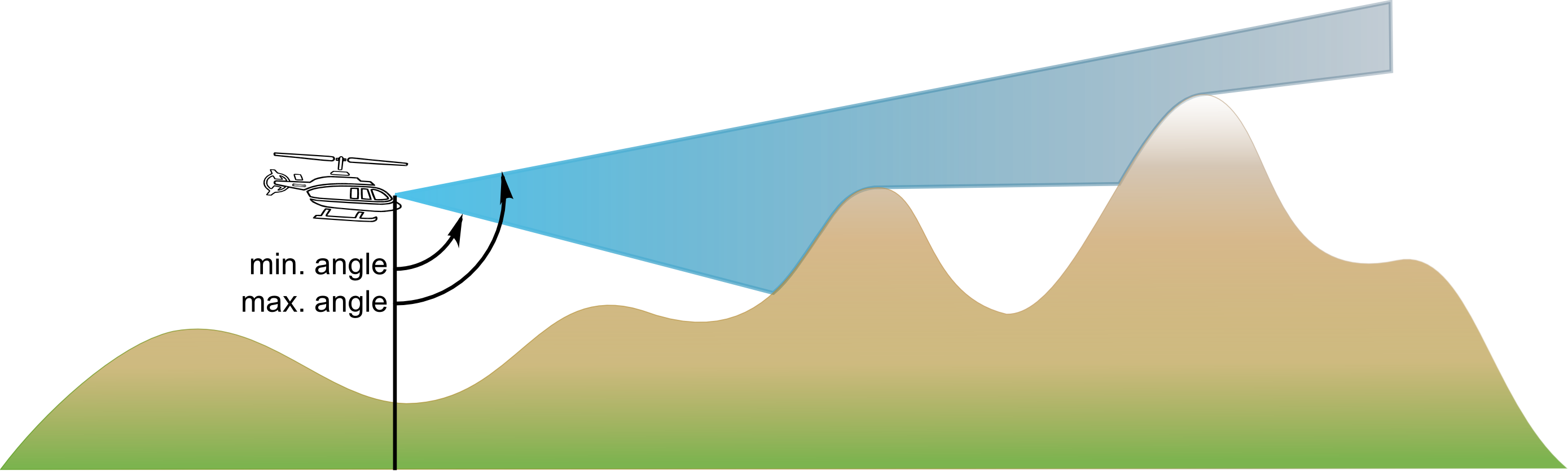
The radar line-of-sight computations need to know in which vertical area one is visible. As illustrated in Figure 6, “The vertical properties of a line-of-sight computation.”, this area is defined by a minimum and maximum vertical angle. Both angles start from zero at the ground to 180 at zenith. These propagation functions also require a terrain elevation provider, providing the altitude of the intermediate points and the K-factor.
The result of the radar line-of-sight calculation is an ILcdPolarMatrixView which contains the altitude above which something can be seen from the center point. Depending on the altitude mode setting
passed to the propagation function this altitude should be interpreted as above ground (relative to terrain data), as above
ellipsoid (relative to centerPointReference) or as above geoid (relative to centerPointReference). This is illustrated in
Figure 7, “How to interpret the result of a line-of-sight computation.”.
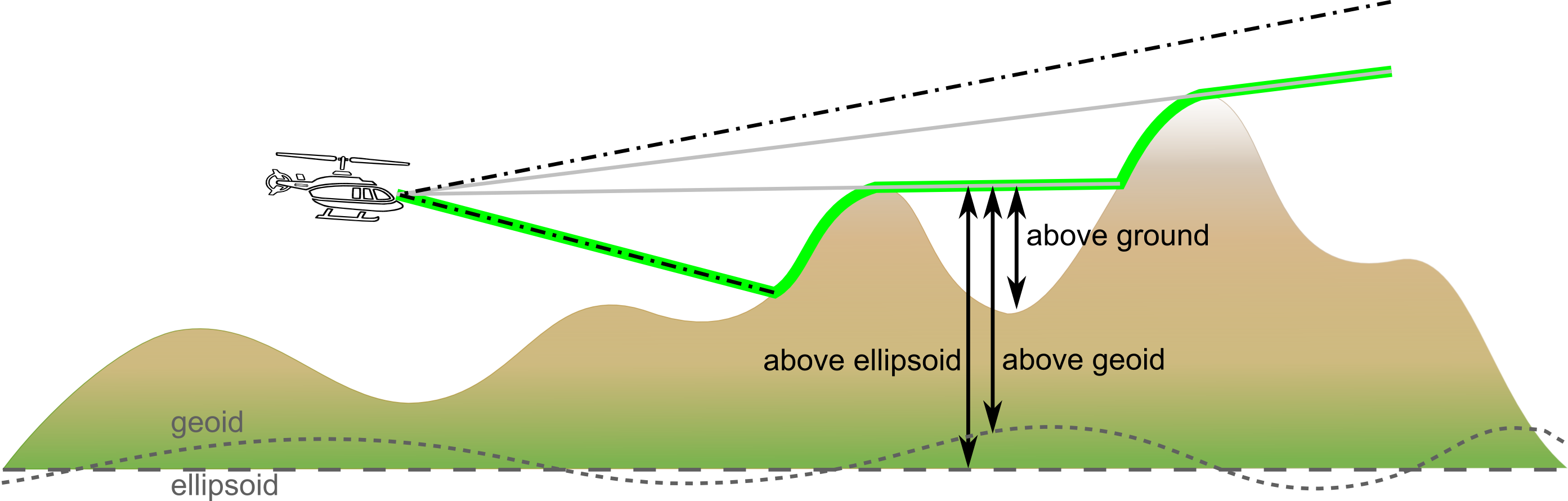
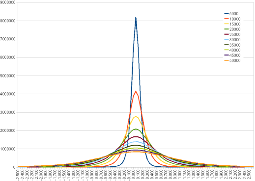
Figure 8, “The geoid variation versus distance.” shows the geoid variations for points within 5km, 10km,… from each other. As can be seen, 90% of the geoid height differences for the 5km values lie within a 20cm interval. The larger the distance, the larger the geoid height differences. For the 50km values, 90% of the geoid height differences lie within a 1,7m interval.
Each ILcdLOSPropagationFunction has its own interpretation of the computed values. Therefore each propagation function can declare their own application
specific special values. The two most common values are:
-
ILcdLOSRadarPropagationFunction.INVISIBLE: the corresponding point is not visible. -
ILcdLOSRadarPropagationFunction.UNKNOWN: due to unknown or invalid values, the visibility of the corresponding point cannot be computed and is unknown.
K-factor
Radar waves are subject to atmospheric refraction. One way to model this is using the effective earth radius method. To account for refraction effects, instead of using the real earth radius, a so-called effective earth radius is used in the calculations. The effective earth radius factor, K, is the ratio of the effective earth radius to the actual earth radius. For line-of-sight calculations that represent visual line-of-sight (i.e. what is visible to a human observer), the K-factor factor should be 1. A K-factor of 1 represents the use-case where there is no atmospheric refraction. For line-of-sight calculations that represent radar waves, the K-factor should typically be greater than 1. When the K-factor is greater than 1, the effective Earth radius becomes larger and the curvature of the Earth, locally, becomes flatter. This means radars can look "beyond the actual horizon". The higher the K-factor, the farther a radar can see beyond the horizon due to atmospheric refraction. A commonly used value is 4/3.
Calculation
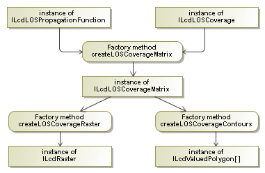
The Terrain Analysis Engine provides the factory class TLcdLOSCoverageFactory which contains the point to environment functionality. It performs the line-of-sight computations according to the defining
properties of the ILcdLOSCoverage and returns the result as a ILcdLOSCoverageMatrix. This result can be used to create an ILcdRaster or a list of ILcdValuedPolygon instances. Figure 9, “Flow of line-of-sight actions.” contains a flow chart of these actions:
LOS point-to-environment example
ShowLOSPanel is an ILcdAction that displays an input panel to create an ILcdRaster, representing a line-of-sight computation. This panel is shown in Figure 10, “Input GUI for point/environment line-of-sight.”.
When you select a point on the map it will be used as the center point of the line-of-sight coverage. The GUI will display the layer the point belongs to and its reference.
The GUI consists of several panels that let you define the input of the line-of-sight computation.
-
the radius panel lets you define the radius and the step length in radial directions
-
the arc panel lets you define the arc extent and the arc step
-
the visibility panel defines the operational parameters of the visibility computation.
The computation algorithm panel lets you define which algorithm the computation should use. You can choose between a normal line-of-sight, a line-of-sight with sky in background or a line-of-sight for a fixed height. The contents of the legend panel changes with the chosen computation algorithm.
The legend panel shows the discrete color model that will be used to render the result of the calculation. This legend should be read as follows:
-
all locations where the intervisibility is unknown are painted in blue.
-
all locations where an object can be seen from an altitude higher than a value between 0 and 1 meter are painted in red.
-
all locations where an object can be seen from an altitude higher than a value between 1 and 50 meter are painted in brown.
-
etc…
For example, if a location is painted brown, the result of the line-of-sight lies between 1 meter and 50 meter. This means that an object at that location at height 0.1 meter shall not be visible from the center point. An object at height 51 meter shall be visible, if the upper limit (the upper dotted line in Figure 2, “The radar propagation result.”) allows it to be visible. An object at height 25 meter shall be visible if the result of the line-of-sight is 25 meter or less.
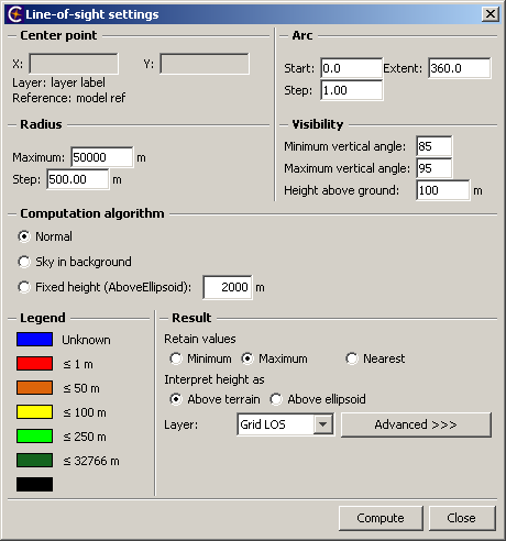
The result panel lets you refine the result of the calculations. It lets you define
-
which values should be retained as result when multiple computations are available for one pixel of the resulting raster
-
how the elevation values returned should be interpreted, above terrain or above ellipsoid
-
the layer in which the result should be put.
In advanced mode you can define the density of the resulting raster. While the radial and arc steps define how many of the underlying points will be sampled (the sampling density), the resulting density defines how many points will be retained in the resulting raster. The higher the sampling density the more accurate the result will be. The higher the resulting density the more precise the result will be. Both these values are limited by the density of the underlying data. It is useless to have a 5 meter sample step if the underlying data value is valid for a 100x100 meter area. The GUI therefore provides two ways to compute a good result density based on the raster data beneath it, either directly or step by step. To compute a density step by step you will have to
-
select a (multilevel-)raster beneath the center point
-
select a raster level of the multilevel raster, if a multilevel raster is chosen
-
retrieve the density of the chosen raster
-
convert the density of the raster, which is expressed in the rasters reference, to the reference of the target layer.
The direct approach follows the same steps but selects the raster and level automatically. Once the result density is computed, it is also possible to choose an optimal values for the arc and radial step, setting the data sampling density as close as possible to the result density.
On clicking "Compute", a new ILcdRaster will be created. The ILcdRaster will not be recomputed automatically when the point that was used to define it is dragged around on the map.
Program: Creating a new line-of-sight ILcdRaster. shows the four steps needed to create a new ILcdRaster by using a TLcdLOSCoverageFactory, based on the properties provided in the GUI. The code can be found in CreateLOSAction. The method arguments are retrieved from the line-of-sight input panel.
ILcdRaster. (from samples/tea/gxy/los/CreateLOSAction)
// Create a circular area to compute the line-of-sight for. An line-of-sight coverage describes
// both the outline of the area and the sampling inside the area.
ILcdLOSCoverage aLOSCoverage = fLOSPanel.createLOSCoverage();

// Create a propagation function describing how the detection wave propagates (visual, radar).
ILcdLOSPropagationFunction los_propagation_function = createLOSPropagationFunction(
    aTerrainElevationProvider,
    aAltitudeMode,
    aMinVerticalAngle,
    aMaxVerticalAngle,
    aComputationAlgorithm,
    aFixedHeightAboveEllipsoid,
    fLOSPanel.retrieveRadarTiltAngle(),
    fLOSPanel.retrieveRadarTiltAzimuth(),
    fLOSPanel.retrieveKFactor()
);

// Compute and create the line-of-sight coverage matrix according to the propagation function
// on the covered area.
ILcdLOSCoverageMatrix los_coverage_matrix = createLOSCoverageMatrix(
    aLOSCoverageFactory,
    los_propagation_function,
    aLOSCoverage,
    (ILcdGeoReference) model.getModelReference()
);

if (fLOSPanel.isOutputAsContours()) {
  // Convert the line-of-sight coverage matrix into a line-of-sight contours.
  ILcdBounded[] contours = createLOSCoverageContour(
      fLOSCoverageFactory,
      los_coverage_matrix,
      aTargetReference,
      aComputationAlgorithm == LOSPanel.PROPAGATION_FUNCTION_FIXED_HEIGHT ? new double[0] : LOSPainter.getLosLevelsInterval(),
      aComputationAlgorithm == LOSPanel.PROPAGATION_FUNCTION_FIXED_HEIGHT ? LOSPainter.getLosLevelsFixedHeight() : LOSPainter.getLosLevelsSpecial());

  model.removeAllElements(ILcdFireEventMode.FIRE_LATER);
  addArrayToModelSFCT(contours, model);

  // Update the painter of the target layer, to use the correct color model.
  ILcdGXYPainter painter = fLOSPanel.retrieveTargetLayer().getGXYPainter(contours[0]);
  if (painter instanceof LOSPainter) {
    ((LOSPainter) painter).setComputationAlgorithm(aComputationAlgorithm);
  }
} else {
  // Convert the line-of-sight coverage matrix into a line-of-sight coverage raster.
  ILcdRaster los_coverage_raster = createLOSCoverageRaster(
      aLOSCoverageFactory,
      los_coverage_matrix,
      aTargetReference,
      aTargetPixelDensity,
      aFillMode,
      aComputationAlgorithm
  );

  // Add the raster to the layer.
  model.removeAllElements(ILcdFireEventMode.FIRE_LATER);
  model.addElement(los_coverage_raster, ILcdFireEventMode.FIRE_NOW);

  // Update the painter of the target layer, to use the correct color model.
  ILcdGXYPainter painter = fLOSPanel.retrieveTargetLayer().getGXYPainter(los_coverage_raster);
  if (painter instanceof LOSPainter) {
    ((LOSPainter) painter).setComputationAlgorithm(aComputationAlgorithm);
  }
}
A propagation function is created with the method from Program: Creating a propagation function.. Depending on the selected computation algorithm, a different propagation function is created.
samples/tea/gxy/los/CreateLOSAction)
private ILcdLOSPropagationFunction createLOSPropagationFunction(
    ALcdTerrainElevationProvider aTerrainElevationProvider,
    TLcdCoverageAltitudeMode aAltitudeMode,
    double aMinVerticalAngle,
    double aMaxVerticalAngle,
    int aComputationAlgorithm,
    double aFixedHeightAboveEllipsoid,
    double aMaxRadarTiltAngle,
    double aMaxRadarTiltAzimuth,
    double aKFactor) {
  TLcdLOSRadarPropagationFunction propagation_function = new TLcdLOSRadarPropagationFunction(
      TLcdEarthRepresentationMode.SPHERICAL_EULER_RADIUS,
      aTerrainElevationProvider,
      aAltitudeMode,
      aMinVerticalAngle,
      aMaxVerticalAngle,
      aMaxRadarTiltAngle,
      aMaxRadarTiltAzimuth,
      aKFactor       // K-factor 1.0 : visual line-of-sight
  );

  if (aComputationAlgorithm == LOSPanel.PROPAGATION_FUNCTION) {
    return propagation_function;
  }
  if (aComputationAlgorithm == LOSPanel.PROPAGATION_FUNCTION_SKY_BACKGROUND) {
    return new TLcdLOSRadarPropagationFunctionSkyBackground(propagation_function, aAltitudeMode);
  }
  if (aComputationAlgorithm == LOSPanel.PROPAGATION_FUNCTION_FIXED_HEIGHT) {
    return new TLcdLOSPropagationFunctionFixedHeight(propagation_function, aFixedHeightAboveEllipsoid, aAltitudeMode);
  }
  throw new IllegalArgumentException("Unknown propagation function.");
}
The function in Program: Creating a line-of-sight coverage. creates the line-of-sight coverage used to compute the line-of-sight matrix. In advanced mode, the best arc and radius steps
is wanted. The flag aAutomaticSteps is set to true and the discretization step sizes are computed automatically.
samples/tea/gxy/los/LOSPanel)
private ILcdLOSCoverage createLOSCoverage(ILcdPoint aCenterPoint,
                                          ILcdGeoReference aCenterPointReference,
                                          double aCenterPointAltitude,
                                          TLcdCoverageAltitudeMode aCenterPointAltitudeMode,
                                          double aRadiusMax,
                                          double aRadiusStep,
                                          double aAngleStart,
                                          double aAngleArc,
                                          double aAngleStep,
                                          boolean aAutomaticSteps,
                                          ILcdGeoReference aTargetReference,
                                          double aSampleDensity,
                                          double aRadialFraction) {
  if (aAutomaticSteps) {
    return new TLcdLOSCoverage(
        aCenterPoint,
        aCenterPointReference,
        aCenterPointAltitude,
        aCenterPointAltitudeMode,
        aRadiusMax,
        aAngleStart,
        aAngleArc,
        aTargetReference,
        aSampleDensity,
        aRadialFraction
    );
  }
  return new TLcdLOSCoverage(
      aCenterPoint,
      aCenterPointReference,
      aCenterPointAltitude,
      aCenterPointAltitudeMode,
      aRadiusMax,
      aRadiusStep,
      aAngleStart,
      aAngleArc,
      aAngleStep
  );
}
The method in Program: Creating a line-of-sight coverage matrix. creates the line-of-sight coverage matrix according to the created propagation function on the covered area.
samples/tea/gxy/los/CreateLOSAction)
private ILcdLOSCoverageMatrix createLOSCoverageMatrix(
    TLcdLOSCoverageFactory aLOSCoverageFactory,
    ILcdLOSPropagationFunction aLOSPropagationFunction,
    ILcdLOSCoverage aLOSCoverage,
    ILcdGeoReference aTargetReference) {

  ILcdGeoReference matrix_reference = aTargetReference;
  // Make sure the matrix reference is a geodetic reference.
  if (!(matrix_reference instanceof ILcdGeodeticReference)) {
    matrix_reference = new TLcdGeodeticReference(ModelFactory.getGeoidGeodeticDatum());
  }

  return aLOSCoverageFactory.createLOSCoverageMatrix(
      aLOSPropagationFunction,
      aLOSCoverage,
      matrix_reference
  );
}
The line-of-sight coverage raster is created using the function from Program: Creating a line-of-sight coverage raster.. Depending on the selected computation algorithm, a different matrix to raster value mapper is used.
samples/tea/gxy/los/CreateLOSAction)
private ILcdRaster createLOSCoverageRaster(TLcdLOSCoverageFactory aLOSCoverageFactory,
                                           ILcdLOSCoverageMatrix aLOSCoverageMatrix,
                                           ILcdGeoReference aTargetReference,
                                           double aTargetPixelDensity,
                                           TLcdCoverageFillMode aFillMode,
                                           int aComputationAlgorithm) {

  ILcdMatrixRasterValueMapper matrix_raster_value_mapper;
  if (aComputationAlgorithm == LOSPanel.PROPAGATION_FUNCTION) {
    matrix_raster_value_mapper = new MatrixRasterValueMapperRadar();
  } else if (aComputationAlgorithm == LOSPanel.PROPAGATION_FUNCTION_SKY_BACKGROUND) {
    matrix_raster_value_mapper = new MatrixRasterValueMapperRadarSkyBackground();
  } else if (aComputationAlgorithm == LOSPanel.PROPAGATION_FUNCTION_FIXED_HEIGHT) {
    matrix_raster_value_mapper = new MatrixRasterValueMapperFixedHeight();
  } else {
    throw new IllegalArgumentException("Unknown propagation function.");
  }

  return aLOSCoverageFactory.createLOSCoverageRaster(
      aLOSCoverageMatrix,
      matrix_raster_value_mapper,
      aTargetReference,
      aTargetPixelDensity,
      aFillMode
  );
}
To create radar coverages, just adjust the K-factor in the construction of the propagation function.
LOS calculation from point to point
Next to the point to area line-of-sight computations, the Terrain Analysis Engine also provides the functionality to compute
a line-of-sight between two points. The coverage between the two points is represented by the class ILcdP2PCoverage. It contains the following properties:
-
startPoint: The point of the point-to-point coverage from which the viewing occurs.
-
startPointReference: The reference in which the start point is defined.
-
startPointAltitude: The altitude of the start point.
-
startPointAltitudeMode: The altitude mode indicating how to interpret the start point altitude. Should the height be interpreted as above object (relative to startPoint), as above ground (relative to terrain data), as above ellipsoid (relative to startPointReference) or as above geoid (relative to startPointReference)?
-
endPoint: The point of the point-to-point coverage to look at.
-
endPointReference: The reference in which the end point is defined.
-
endPointAltitude: The altitude of the end point.
-
endPointAltitudeMode: The altitude mode indicating how to interpret the end point altitude. Should the height be interpreted as above object (relative to endPoint), as above ground (relative to terrain data), as above ellipsoid (relative to endPointReference) or as above geoid (relative to endPointReference)?
-
stepSize: The discretization step used for finding intermediate points during the point-to-point computation.
As in the previous section, a propagation function is required in order to compute the point-to-point visibility. The propagation
function, represented by the interface ILcdP2PPropagationFunction, will calculate the visibility between the two defining points and it will return the result as a TLcdVisibilityStatus. The Terrain Analysis Engine provides two implementations of the point-to-point propagation function:
-
TLcdP2PRadarPropagationFunction: computes the visibility between the two defining points. The visual line is drawn as a green line in Figure 11, “The radar propagation result.”, because the helicopter is visible from the tower.
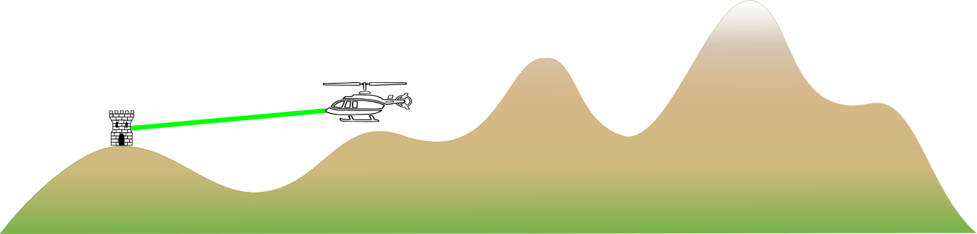 Figure 11. The radar propagation result.
 -
TLcdP2PRadarPropagationFunctionSkyBackground: computes the visibility with the sky as background between the two defining points. This function requires a distance after the second point in which the terrain is taken into account as possible background. The visual line is draw as a red line in Figure 12, “The sky in background propagation result.”, because the helicopter is not visible from the tower with the sky in the background.
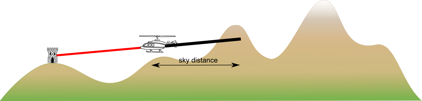 Figure 12. The sky in background propagation result.
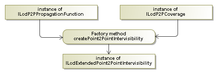
The Terrain Analysis Engine provides the factory class TLcdP2PCoverageFactory to create a point-to-point intervisibility object. It performs the calculations according to the defining properties of the
ILcdP2PCoverage and returns the result as an ILcdExtendedPoint2PointIntervisibility. Figure 13, “Flow of point-to-point actions.” contains a flow chart of these actions:
LOS point-to-point calculation example
ShowPToPPanel displays a GUI to produce input for the TLcdP2PCoverageFactory to create an ILcdExtendedPoint2PointIntervisibility, see Figure 14, “Input GUI for point-to-point intervisibility.”.
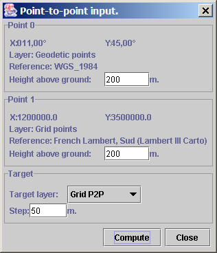
Point-to-point intervisibility computations require two points as input. These two points are entered as the points selected on the map, one after another. Upon new selection the oldest point will be replaced.
The GUI lets you enter the values for the height above ground of both points and the step that should be taken to find intermediate points.
In the example, the points will be connected with a line or an arrow according to the following hierarchy. If the points are moved around on the map, their intervisibility is automatically updated.
-
an orange line with an arrow indicating the view direction: the visibility with sky in background could not be computed, due to unknown or invalid elevation data.
-
an orange line: the visibility could not be computed, due to unknown or invalid elevation data.
-
a blue line with an arrow indicating the view direction: the second point is visible from the first point with the sky in background.
-
a green line: the second point is visible from the first point without sky in background.
-
a red line: the two points are not visible to each other.
Program: Creating a new point-to-point ILcdExtendedPoint2PointIntervisibility. shows the three steps needed to create a new ILcdExtendedPoint2PointIntervisibility by using a TLcdP2PCoverageFactory, based on the properties provided in the GUI. The code can be found in CreateP2PAction. The method arguments are retrieved from the point-to-point input panel.
ILcdExtendedPoint2PointIntervisibility. (from samples/tea/gxy/los/CreateP2PAction)
// Create a linear area to compute the line-of-sight for. A point-to-point coverage describes
// both the defining points and the sampling step.
ILcdP2PCoverage aP2PCoverage = fP2PPanel.createP2PCoverage();

// Create a propagation function describing how the detection wave propagates (visual, radar).
ILcdP2PPropagationFunction p2p_propagation_function = createP2PPropagationFunction(
    aTerrainElevationProvider,
    aComputationAlgorithm
);

// Create the intervisibility according to the 'radar' propagation function on the covered area.
ILcdExtendedPoint2PointIntervisibility p2p_intervisibility = createExtendedPoint2PointIntervisibility(
    aP2PCoverageFactory,
    p2p_propagation_function,
    aP2PCoverage,
    aTerrainElevationProvider,
    aTargetReference
);
The function in Program: Creating a point-to-point coverage. creates the point-to-point coverage used to compute the intervisibility between the two defining points.
samples/tea/gxy/los/P2PPanel)
private ILcdP2PCoverage createP2PCoverage(ILcdPoint aStartPoint,
                                          ILcdGeoReference aStartPointReference,
                                          double aStartPointAltitude,
                                          TLcdCoverageAltitudeMode aStartPointAltitudeMode,
                                          ILcdPoint aEndPoint,
                                          ILcdGeoReference aEndPointReference,
                                          double aEndPointAltitude,
                                          TLcdCoverageAltitudeMode aEndPointAltitudeMode,
                                          double aStepSize) {
  return new TLcdP2PCoverage(
      aStartPoint,
      aStartPointReference,
      aStartPointAltitude,
      aStartPointAltitudeMode,
      aEndPoint,
      aEndPointReference,
      aEndPointAltitude,
      aEndPointAltitudeMode,
      aStepSize
  );
}
A propagation function is created with the method from Program: Creating a propagation function.. Depending on the selected computation algorithm, a different propagation function is created.
samples/tea/gxy/los/CreateP2PAction)
private ILcdP2PPropagationFunction createP2PPropagationFunction(
    ALcdTerrainElevationProvider aTerrainElevationProvider,
    int aComputationAlgorithm) {
  if (aComputationAlgorithm == P2PPanel.PROPAGATION_FUNCTION) {
    return new TLcdP2PRadarPropagationFunction(
        TLcdEarthRepresentationMode.SPHERICAL_EULER_RADIUS,
        aTerrainElevationProvider,
        1.0       // K-factor 1.0 : visual point-to-point
    );
  }
  if (aComputationAlgorithm == P2PPanel.PROPAGATION_FUNCTION_SKY_BACKGROUND) {
    return new TLcdP2PRadarPropagationFunctionSkyBackground(
        TLcdEarthRepresentationMode.SPHERICAL_EULER_RADIUS,
        aTerrainElevationProvider,
        1.0,      // K-factor 1.0 : visual point-to-point
        50000     // SkyDistance : distance after the second point in which the terrain
                  //               is taken into account as possible background.
    );
  }
  throw new IllegalArgumentException("Unknown propagation function.");
}
The point-to-point intervisibility is created according to the created propagation function on the created coverage using the function from Program: Creating a point-to-point intervisibility..
samples/tea/gxy/los/CreateP2PAction)
private ILcdExtendedPoint2PointIntervisibility createExtendedPoint2PointIntervisibility(
    TLcdP2PCoverageFactory aP2PCoverageFactory,
    ILcdP2PPropagationFunction aP2PPropagationFunction,
    ILcdP2PCoverage aP2PCoverage,
    ALcdTerrainElevationProvider aTerrainElevationProvider,
    ILcdGeoReference aTargetReference) {
  return aP2PCoverageFactory.createPoint2PointIntervisibility(
      aP2PPropagationFunction,
      aP2PCoverage,
      aTargetReference,
      aTerrainElevationProvider
  );
}
The code to create a radar coverage is very similar, just adjust the K-factor in the construction of the propagation function.
LOS calculation with OpenCL hardware acceleration
This section discusses how to perform Line-of-Sight calculations using a device that supports OpenCL. Using hardware acceleration can greatly increase the performance of LOS calculations, but requires OpenCL compatible devices to be present in the system running the calculations.
LOS calculation from point to environment
Hardware accelerated calculation
The Terrain Analysis Engine allows you to calculate Line-of-Sight coverages for points. The main class to use for this
is TLspLOSCalculator, which allows you to calculate Line-of-Sight
for a given set of TLspLOSProperties. A LOS properties object
contains the following properties:
-
Center point: The point around which the area is covered.
-
Center point reference: The reference in which the center point is defined.
-
Center point altitude: The altitude of the center point.
-
Center point altitude mode: The altitude mode indicating how to interpret the center point altitude.
-
Maximum radius: The radial extent of the coverage area.
-
Radius step: The radial discretization step used to find the computation points.
-
Radius sample distances: The maximum radius and radius step implicitly define the radius sample distances. These are the distances from the center of the coverage at which to sample to perform the computation. If you want to define a custom sampling scheme, you can use this property instead. This is for example useful to increase the range of a coverage without impacting performance and accuracy much by using larger steps farther away from the center.
-
Start angle: The starting angle of the arc which defines the coverage area.
-
Arc angle: The angular extent of the arc which defines the coverage area.
-
Angle step: The angular discretization step used to find the computation points.
-
Minimum vertical angle: The angular lower bounds for the cone of silence around the observer
-
Maximum vertical angle: The angular upper bounds for the cone of silence around the observer
-
Maximum radar tilt angle: The maximum radar tilt angle
-
Maximum radar tile azimuth: The azimuth where the maximum radar tilt angle occurs
-
The K-factor: A factor indicating the reflection of radar waves on the atmosphere.
The TLspLOSCalculator works in a similar way as the non-hardware accelerated TLcdLOSCoverageFactory, in the sense that it samples each radius from start to finish point. The difference is that the TLspLOSCalculator does this in parallel for all radii at once.
The TLspLOSCalculator contains 3 basic methods to create, update and dispose of
ILcdLOSCoverageMatrix instances. For performance reasons, it is recommended to update existent ILcdLOSCoverageMatrix instances instead of creating new and disposing of old ones, where possible.
To set the output altitude mode of a Line-of-Sight calculation, use the setAltitudeMode() method on the TLspLOSCalculator. The following output modes are supported:
-
ABOVE_GEOID: The values in the coverage matrix are relative to the geoid of the target reference
-
ABOVE_GROUND_LEVEL: The values in the coverage matrix are relative to the height of the terrain of the given altitude provider
-
ABOVE_ELLIPSOID: The values of the coverage matrix are relative to the ellipsoid of the target reference
Visualization in a Lightspeed view
To paint any ILcdLOSCoverageMatrix, that is either the result of hardware accelerated or non-hardware accelerated OpenCL computations, in a Lightspeed view,
you can use TLspShapeLayerBuilder and configure it with a TLspLOSCoveragePainter. This painter is equipped with the functionality to create a full 3D mesh out of any ILcdLOSCoverageMatrix.
The styling of a ILcdLOSCoverageMatrix can be done using a TLspLOSCoverageStyle. This class allows you to use a TLcdColorMap on a coverage matrix. The color map maps coverage matrix values to colors.
Coverage matrices can also be draped on the terrain. If they are not draped, each point in the coverage matrix will have an elevation that is based on the actual value in the coverage matrix. Values in between sample points are interpolated. When a coverage matrix is visualized in a non-draping manner, the resulting 3D mesh signifies the area in which points are invisible to the observer, i.e. an area of invisibility.
Note that non-draping visualization is only supported by ILcdLOSCoverageMatrix created by the TLspLOSCalculator.
LOS point-to-environment example
The functionality is demonstrated in the samples.tea.lightspeed.los example. The sample creates two layers: An input shape layer and an output LOS layer. The input shape layer contains an arcband
shape, which is used to generate the necessary TLspLOSProperties parameters, such as radius, center position, arc size, and so on. This is just one of the ways to obtain a set of LOS properties,
but it is not imposed.
Program: Creation of an altitude provider for Line-of-Sight. shows how the sample creates an altitude provider based on a view. Program: Deriving the LOS properties from an input shape. demonstrates how the sample obtains the necessary properties from the input shape. The altitude matrix and properties are then used in Program: Creating a new coverage matrix. to create a new LOS coverage, which can be painted by the
samples/tea/lightspeed/los/MainPanel)
ILcdEarthTileSet elevationTileSet = view.getServices().getTerrainSupport().getElevationTileSet();
TLcdEarthTileSetElevationProvider elevationProvider = new TLcdEarthTileSetElevationProvider(elevationTileSet, 1, 0, 64);
elevationProvider.setForceAsynchronousTileRequests(false);
int tileLevel = 10;
elevationProvider.setMaxSynchronousLevel(tileLevel);
elevationProvider.setMaxTileLevel(tileLevel);
EarthTerrainElevationAdapter earthTerrainElevationAdapter = new EarthTerrainElevationAdapter(elevationProvider);samples/tea/lightspeed/los/view/LOSLayerFactory)
/**
 * Converts a <code>LOSCoverageInputShape</code> to a {@link com.luciad.tea.lightspeed.los.TLspLOSProperties TLspLOSProperties}
 * object.
 * @param aLOSCoverageInputShape an input shape to
 * @return a properties object based on the given input shape.
 */
private TLspLOSProperties createLOSProperties(LOSCoverageInputShape aLOSCoverageInputShape) {
  TLspLOSProperties losProperties = new TLspLOSProperties();
  losProperties.setAngleArc(aLOSCoverageInputShape.getArcAngle());
  double angleStart = 90.0 - (aLOSCoverageInputShape.getStartAngle() + aLOSCoverageInputShape.getArcAngle());
  losProperties.setAngleStart(angleStart); // Small correct because an arc band's start angle is w.r.t. 3 o'clock
  losProperties.setAngleStep(aLOSCoverageInputShape.getAngleStep());
  losProperties.setMinVerticalAngle(aLOSCoverageInputShape.getMinVerticalAngle());
  losProperties.setMaxVerticalAngle(aLOSCoverageInputShape.getMaxVerticalAngle());

  double centerPointAltitude = fAltitudeProvider.retrieveAltitudeAt(aLOSCoverageInputShape.getCenter(), (ILcdGeoReference) fInputModel.getModelReference());
  if (!fAltitudeProvider.getAltitudeDescriptor().isSpecialValue(centerPointAltitude)) {
    centerPointAltitude += aLOSCoverageInputShape.getCenterPointHeightOffset();
  } else {
    centerPointAltitude = aLOSCoverageInputShape.getCenterPointHeightOffset();
  }
  losProperties.setCenterPoint(new TLcdXYZPoint(aLOSCoverageInputShape.getCenter().getX(),
                                                aLOSCoverageInputShape.getCenter().getY(),
                                                centerPointAltitude));

  // The input shape is added to the input model, so it is defined in the same reference
  losProperties.setCenterPointReference((ILcdGeoReference) fInputModel.getModelReference());
  losProperties.setRadiusStep(aLOSCoverageInputShape.getRadiusStep());
  losProperties.setRadius(aLOSCoverageInputShape.getMaxRadius());
  if (aLOSCoverageInputShape.getRadiusStepIncrease() != 0) {
    // Define custom radius distances (from the center) at which to sample.
    losProperties.setRadiusSampleDistances(createRadiusSampleDistances(aLOSCoverageInputShape));
  } else {
    losProperties.setRadiusSampleDistances(null);
  }
  losProperties.setCenterPointAltitudeMode(TLcdCoverageAltitudeMode.ABOVE_ELLIPSOID);
  return losProperties;
}
The sample keeps a map for each input shape and maps it to a ILcdLOSCoverageMatrix. When the input shape is modified, it updates the related ILcdLOSCoverageMatrix. The layer factory
listens to model changes in the input model and calls the code in Program: Updating an existent coverage matrix. to update the output coverage.
samples/tea/lightspeed/los/view/LOSLayerFactory)
/**
 * This method converts the given <code>LOSCoverageInputShape</code> into
 * a <code>TLspLOSProperties</code>, which it then passes to the <code>TLspLOSCalculator</code>
 * of this object. The resulting <code>ILcdLOSCoverageMatrix</code> is returned.
 *
 * @param aLOSCoverageInputShape A LOS coverage input shape that contains all necessary parameters
 *
 * @return An <code>ILcdLOSCoverageMatrix</code> that can be painted with <code>TLspLOSCoveragePainter</code>,
 *         based on the parameters of the input shape.
 */
private ILcdLOSCoverageMatrix createLOSOutputObject(LOSCoverageInputShape aLOSCoverageInputShape) {
  TLspLOSProperties losProperties = createLOSProperties(aLOSCoverageInputShape);
  return fLOSCalculator.calculateLOS(losProperties, fAltitudeProvider, (ILcdGeoReference) fOutputModel.getModelReference());
}samples/tea/lightspeed/los/view/LOSLayerFactory)
/**
 * Updates the output object that was constructed using the given input shape.
 * @param aLOSCoverageInputShape An input shape that was previously used to create a LOS output object.
 */
private void updateLOSOutputObject(LOSCoverageInputShape aLOSCoverageInputShape) {
  TLspLOSProperties losProperties = createLOSProperties(aLOSCoverageInputShape);
  ILcdLOSCoverageMatrix losOutputObject = fInputToOutputMap.get(aLOSCoverageInputShape);
  if (losOutputObject != null) {
    fLOSCalculator.updateLOSCalculationSFCT(losProperties, fAltitudeProvider, (ILcdGeoReference) fOutputModel.getModelReference(), losOutputObject);
  }
}
The sample uses the LOSCoverageStyler to style any LOS coverages in the painter. This simple implementation of the ILspStyler interface uses the same TLspLOSCoverageStyle for every coverage matrix painted by the coverage painter.
The style is set by the LOSStylePanel. The panel appears in the sample whenever an input shape is selected. It allows you to modify the color map as well as the
draping setting.
Besides the style panel, there is also a LOSParametersPanel, which allows you to set specific parameters that can’t be edited through the regular user interface, such as step size or
angle sampling step.
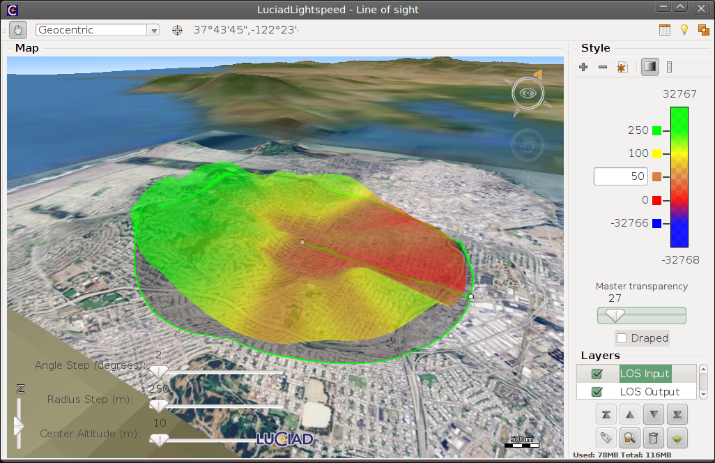
Figure 15, “The sample included with the Terrain Analysis Engine component.” shows a screenshot of the sample in action.