Class FeatureCanvas.Icon3DDrawCommand
- All Implemented Interfaces:
AutoCloseable
- Enclosing class:
FeatureCanvas
The key parts of an Icon3DDrawCommand are:
- A 3D mesh, such as a plane, a building, and so on in .GLTF or .GLB format
- A set of transformation parameters to align the 3D mesh in its own local origin:
scale,rotation, andtranslation - Transformation parameters to align the 3D mesh in the world:
orientation
By default, the following assumptions are made about the 3D mesh in LuciadCPillar:
- The Y-axis points forward: the part of the mesh that is considered the front is pointing in the positive Y-direction
- The X-axis points right: the right side of the mesh is facing the positive X-direction
- The Z-axis points up: the top of the mesh is facing the positive Z-direction
- The mesh is defined in meters
- The anchor point or center point of the mesh is at the XYZ-location (0,0,0)
The glTF format uses a Y-up axis, this is automatically converted to the axis used in LuciadCPillar. Should your mesh not be aligned as intended, you can use the scale, rotation, and translation parameters.
Example: you have a 3D aircraft mesh. The aircraft is defined in millimeters and it points to the halfway point between the X and Y direction.
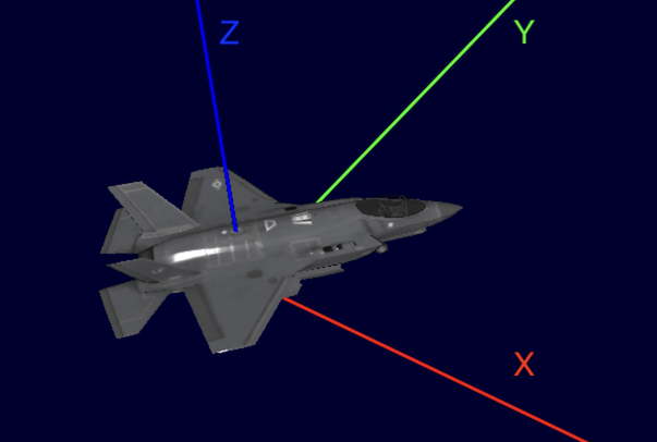
If you want to align this mesh with our assumptions, you must scale by a factor of 1/1000, and rotate by 45 degrees about the Z-axis:
This results in:
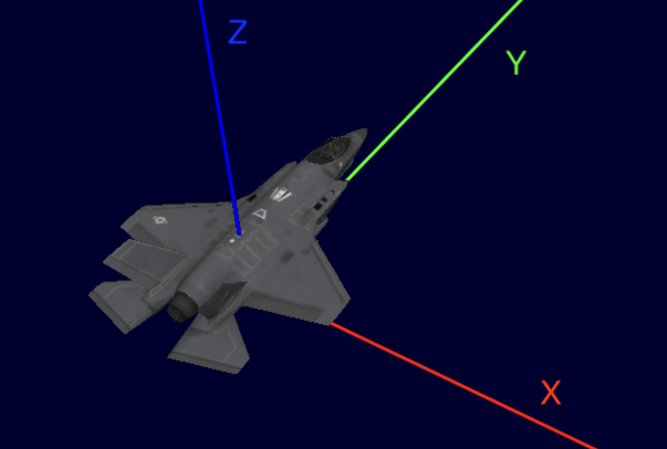
Once you have your mesh correctly aligned in its own local reference using rotation, scale and translation, you are ready to orient the 3D mesh in the world. By default, the position of the mesh is parallel to the surface of the ellipsoid. The Y-direction points towards the north and the X-direction points towards the east.
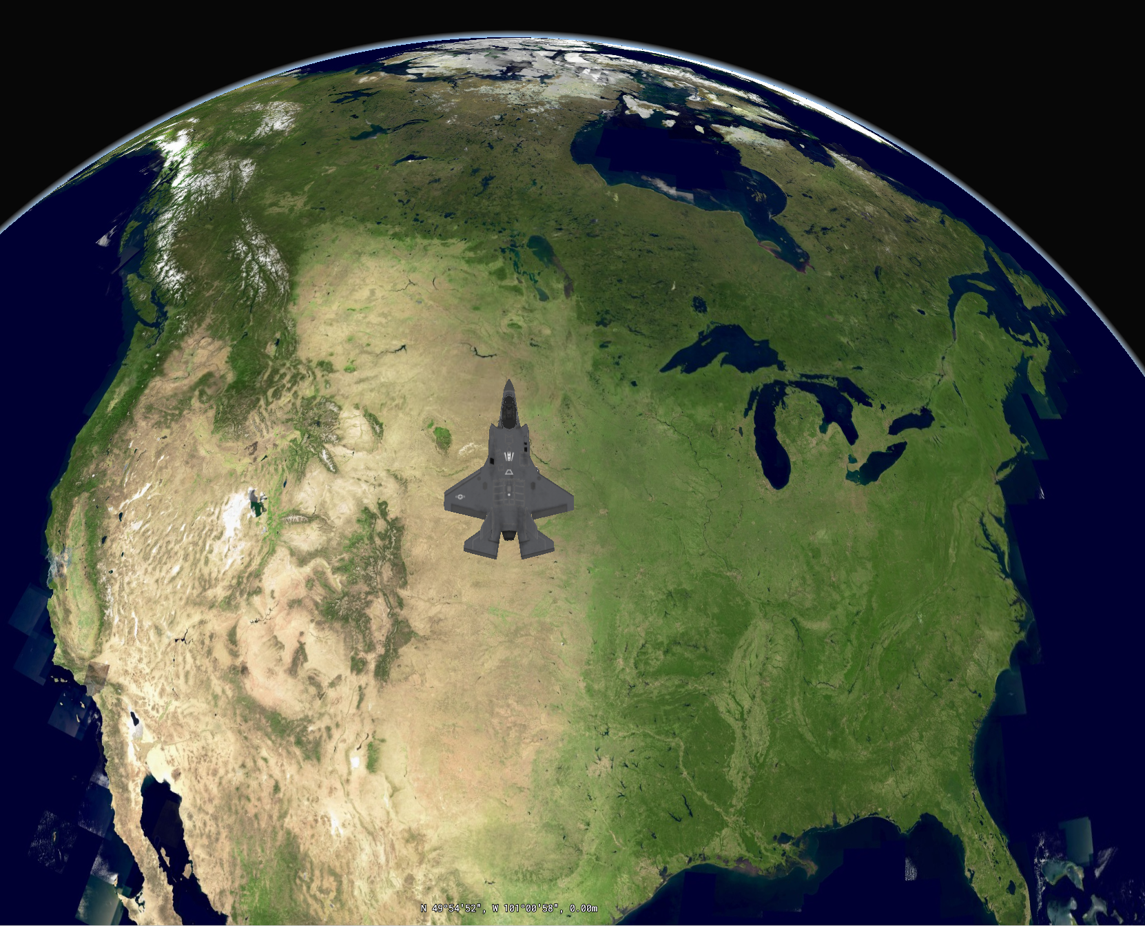
You can change the heading, pitch and roll of the mesh by adjusting the orientation. Example: you want your aircraft to point to the east. You must make sure that its heading is 90 degrees, measured clockwise from the north.
This orientation results in:
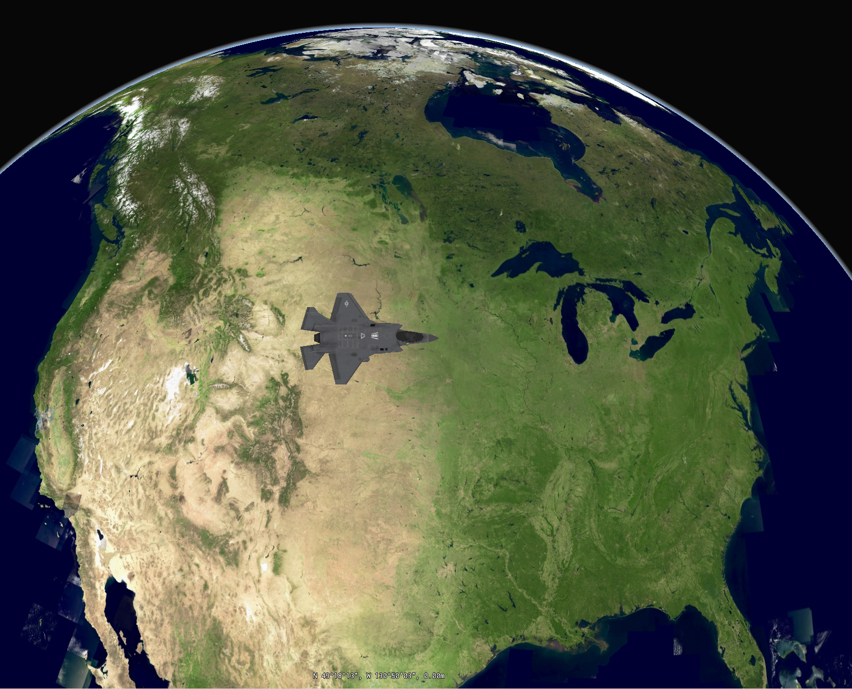
In addition to heading, an orientation object allows you to specify pitch and roll. See below for the effect of those parameters on the aircraft.
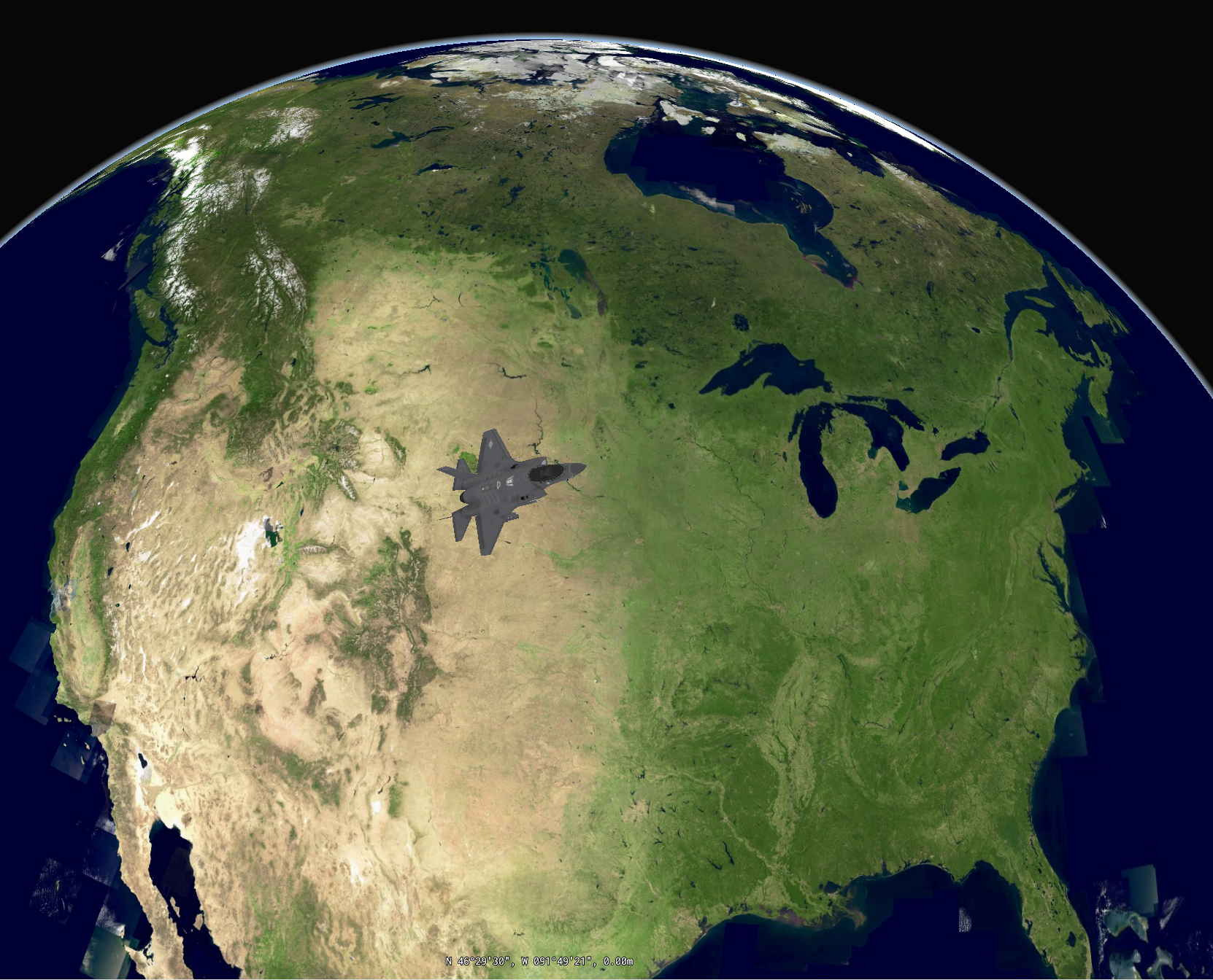
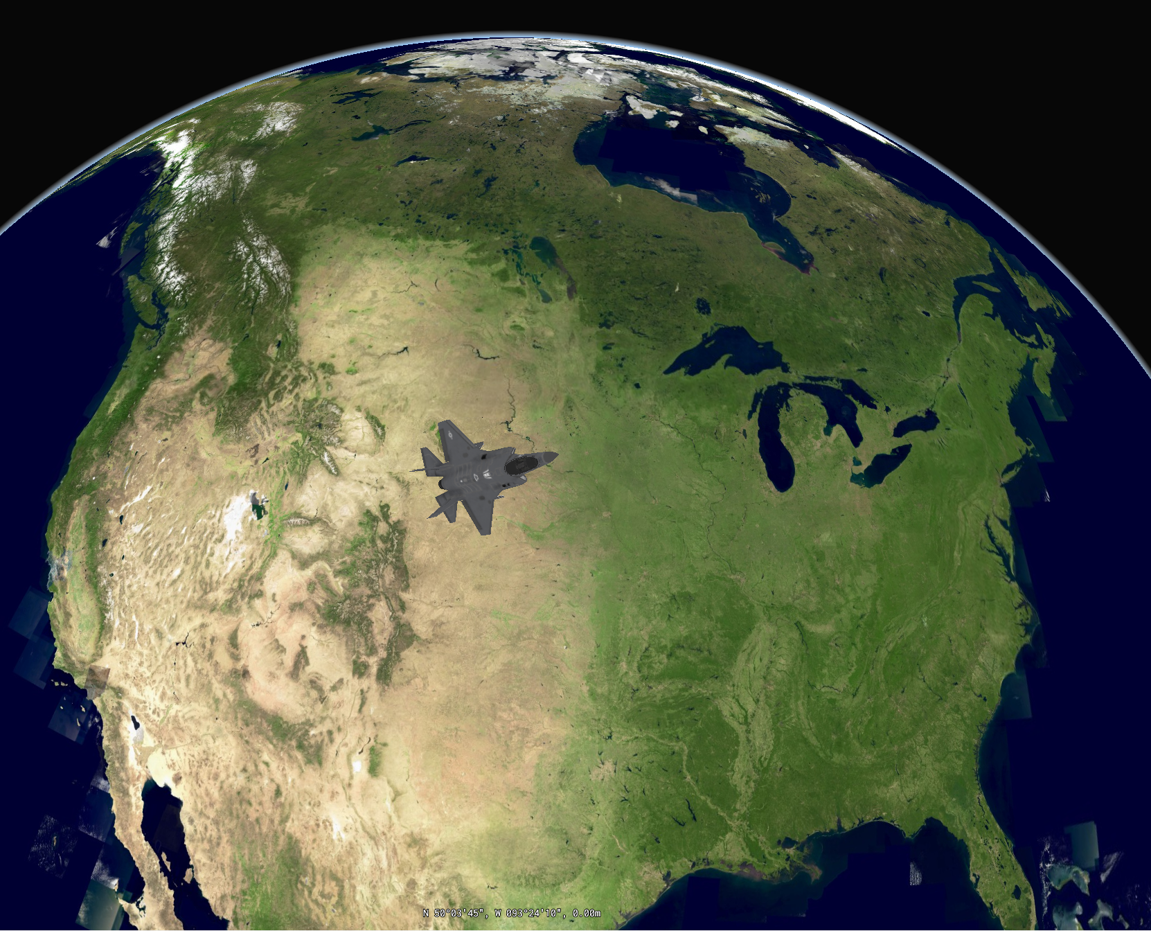
In the case where your gltf mesh is corrupted or cannot be decoded, a RuntimeError is thrown later on in the process.
- Since:
- 2023.1
-
Method Summary
Modifier and TypeMethodDescriptionvoidclose()color(android.graphics.Color color) The color of the 3D icon.facetCulling(FacetCullingType facetCulling) This setting determines which side of the surfaces (facets) that make up a mesh are omitted (culled) from the rendering result.protected voidfinalize()orientation(Azimuth heading, Angle pitch, Angle roll) Defines the orientation of a 3D icon.The location where the 3D icon will be drawn.queryable(boolean queryable) Indicates whether or not the 3D icon should be considered when aMap#queryFeaturesis requested.Defines the rotation angle in degrees around the various axes of the 3D icon in its local reference.scale(double scaleX, double scaleY, double scaleZ) Defines the factor by which the 3D icon is scaled along the various axes of the 3D icon's local reference.Specifies the path to the 3D icon to draw.voidsubmit()Submits this draw command.translation(double translateX, double translateY, double translateZ) Defines the distance by which coordinates are translated in the various axes direction of the 3D icon local reference.transparency(boolean transparency) Indicates whether transparent surfaces should be painted transparently.
-
Method Details
-
finalize
protected void finalize() -
close
public void close()- Specified by:
closein interfaceAutoCloseable
-
source
@NotNull public FeatureCanvas.Icon3DDrawCommand source(@NotNull String source) throws IllegalArgumentException Specifies the path to the 3D icon to draw.This property is mandatory.
- Parameters:
source- A path to a .GLTF or .GLB file.- Returns:
- this
Icon3DDrawCommand. - Throws:
IllegalArgumentException- if the source file does not exists.
-
position
@NotNull public FeatureCanvas.Icon3DDrawCommand position(@NotNull Point position) throws NullPointerException The location where the 3D icon will be drawn.This property is mandatory.
- Parameters:
position- the position of the 3D coordinate.- Returns:
- this
Icon3DDrawCommand - Throws:
NullPointerException- when no position has been set.
-
queryable
Indicates whether or not the 3D icon should be considered when aMap#queryFeaturesis requested.This property is optional.
The default is true.
- Parameters:
queryable- true if the icon should be considered.- Returns:
- this
Icon3DDrawCommand.
-
scale
@NotNull public FeatureCanvas.Icon3DDrawCommand scale(double scaleX, double scaleY, double scaleZ) throws IllegalArgumentException Defines the factor by which the 3D icon is scaled along the various axes of the 3D icon's local reference.Scale can be used to convert a 3D icon from its local unit-of-measure to meters. By default, we assume that a 3D icon is defined in meters. If this is not the case, scale can be used to enlarge or shrink the 3D icon to fit its own unit of measure. This property is optional. Note that the scale must be a positive, non-zero floating point value.
- Parameters:
scaleX- The scale around the x-axis. Default is 1.scaleY- The scale around the y-axis. Default is 1.scaleZ- The scale around the z-axis. Default is 1.- Returns:
- this
Icon3DDrawCommand - Throws:
IllegalArgumentException- if a value equal to or smaller than 0 is provided
-
translation
@NotNull public FeatureCanvas.Icon3DDrawCommand translation(double translateX, double translateY, double translateZ) Defines the distance by which coordinates are translated in the various axes direction of the 3D icon local reference.This property should be used to center a 3D icon to (0,0,0) in its own local cartesian reference. This allows you to set the anchorpoint of the 3D icon, which is useful when you want to rotate the 3D icon around a specific point. This property is optional.
- Parameters:
translateX- The translation around the x-axis. Default is 0.translateY- The translation around the y-axis. Default is 0.translateZ- The translation around the z-axis. Default is 0.- Returns:
- this
Icon3DDrawCommand
-
rotation
@NotNull public FeatureCanvas.Icon3DDrawCommand rotation(@NotNull Angle rotationX, @NotNull Angle rotationY, @NotNull Angle rotationZ) Defines the rotation angle in degrees around the various axes of the 3D icon in its local reference.Rotation happens around (0,0,0) in the local reference of the 3D icon. By default the rotation is 0 for all axis. This property is optional.
The difference between
orientationand rotation is thatorientationis defined in the world reference. Rotation on the other hand is defined in the local reference of the mesh. You should use rotation to align the mesh to its axes, before it is added to the world. You should useorientationto point the mesh in a certain world direction, after it has been added to the world.- Parameters:
rotationX- The rotation around the x-axis. Default is 0.rotationY- The rotation around the y-axis. Default is 0.rotationZ- The rotation around the z-axis. Default is 0.- Returns:
- this
Icon3DDrawCommand
-
orientation
@NotNull public FeatureCanvas.Icon3DDrawCommand orientation(@NotNull Azimuth heading, @NotNull Angle pitch, @NotNull Angle roll) Defines the orientation of a 3D icon.It is defined by the following angles:
- heading: The angle wrt. the north direction. A value of 0 points the 3D icon towards the North pole. The angle increases in clockwise direction, e.g. +90 points the 3D icon to the east.
- pitch: The angle wrt. the horizon (aka. "tilt"). A value of 0 points the 3D icon towards the horizon (i.e. horizontally). -90 points the 3D icon straight down towards the ground and +90 points the 3D icon straight up, towards the sky.
- roll: A rotation around the 3D icon's forward direction (aka "bank"). Negative angles bank the 3D icon left; positive angles bank the 3D icon right.
The orientation is applied as roll first, then pitch and lastly heading.
This property is optional.
The difference between orientation and rotation is that orientation is defined in the world reference.
Rotationon the other hand is defined in the local reference of the mesh. You should userotationto align the mesh to its axes, before it is added to the world. You should use orientation to point the mesh in a certain world direction, after it has been added to the world.- Parameters:
heading- A number defining the heading in degrees. Default value is 0 (north).pitch- A number defining the pitch in degrees. Default value is 0.roll- A number defining the roll in degrees. Default value is 0.- Returns:
- this
Icon3DDrawCommand
-
transparency
Indicates whether transparent surfaces should be painted transparently.A transparent surface is a surface with either a color or a texture with an alpha channel value lower than 1. The transparency of a surface is not auto-detected.
If you set this property to true, LuciadCpillar considers the 3D icon to have transparent surfaces, and renders it as such. If you set it to false, there is no guarantee that LuciadCpillar renders the transparent surfaces of the 3D Icon properly.
For example, if you set transparency to false for this jet with a transparent cockpit, it has a see-through hole where the cockpit should be:
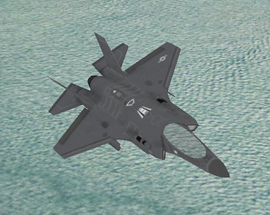
Transparency Off 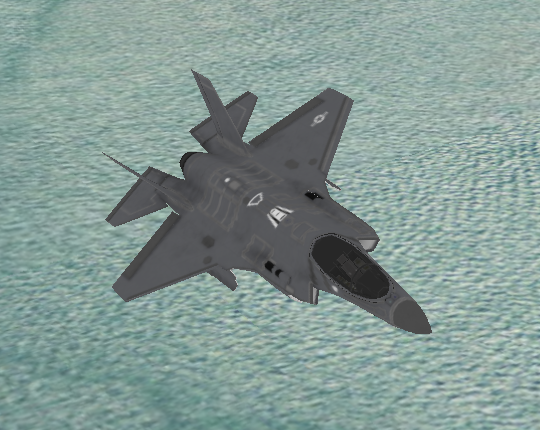
Transparency On Note that setting this flag to true might affect performance. Use it for meshes with transparent surfaces only. Drawing a mesh with the transparency flag enabled comes at a cost. It amounts to drawing the mesh twice.
- Parameters:
transparency- if the mesh has transparent component or not. The default value for transparency is false.- Returns:
- this
Icon3DDrawCommand
-
color
The color of the 3D icon.Note that if the mesh contains textures, this color will act as a modulation color. This can be useful for selection.
- Parameters:
color- the color to apply. If not set, The default value for this property is opaque white: rgba(255, 255, 255, 255).- Returns:
- this
Icon3DDrawCommand
-
facetCulling
@NotNull public FeatureCanvas.Icon3DDrawCommand facetCulling(@NotNull FacetCullingType facetCulling) This setting determines which side of the surfaces (facets) that make up a mesh are omitted (culled) from the rendering result.When rendering meshes, all surfaces that make up the mesh face a certain direction. This direction is often called the normal direction. This normal is used to determine if the surface is being seen from the front or the back. When rendering objects that have no holes in them, it is only possible to see the front of all surfaces. Graphics pipelines therefore often don't render the back sides of those surfaces to speed up rendering.
Apart from performance, some applications are made possible by enabling back-face culling. Consider for example a mesh that represents a room. Its normals would all point to the inside of the room. When enabling back-face culling, you can see the walls and floor of the room, without having to move the camera inside the room itself.
In some cases however, enabling back-face culling (i.e. not rendering the back-side of surfaces) can have undesired artifacts. This can for example happen:
- for objects with incorrect normals. In that case, you will for example only see the inside of a mesh instead of the outside
- for objects with holes in them. In that case, you won't be able to see the inside of the mesh, even when looking through the hole
Both can be resolved by disabling culling.
By default, no culling takes place and both sides of a surface are painted.
- Parameters:
facetCulling- the facet culling type to use- Returns:
- this builder
-
submit
Submits this draw command.Nothing will be painted if the draw command is not submitted.
- Throws:
IllegalStateException- when there are missing 3D icon command calls or the command is already submitted.
-