In LuciadRIA , you can draw a 3D object as a mesh.
A mesh is a collection of three-dimensional points, lines, and surfaces that describe the shape of the object.
You can paint all 3D icons using a FeaturePainter in combination with an Icon3DStyle.
To style a feature as a 3D icon mesh, you call drawIcon3D on a view/style/GeoCanvas instance.
The FeaturePainter paint methods pass the GeoCanvas instance as the first parameter.
const painter = new FeaturePainter();
painter.paintBody = function(geoCanvas, feature, shape, map, layer, state) {
  const icon3DStyle = {
    meshUrl: "car.gltf"
  };
  geoCanvas.drawIcon3D(shape, icon3DStyle);
};
Icon3DStyle gives you access to all kinds of options, but the one thing you must specify is the mesh to paint.
You can do so by:
-
Specifying a URL to a GL Transmission Format (glTF) file with
meshUrl. glTF files are JSON files that describe the structure and composition of a scene containing 3D models. In this case, they describe the meshes of the 3D objects that appear in the scene.meshUrlmust point to a glTF file. You can specify all kinds of mesh properties in the glTF format. -
Creating a simple configurable mesh using
Simple3DMeshFactory. -
Creating a mesh at the triangle level with
MeshFactory:Program: Configuring the style with a mesh created bySimple3DMeshFactory(fromsamples/icons3d/StyleFactory.js)return { mesh: create3DDome(1000, 50), color: "rgba(255, 55, 55, 0.5)", rotation: { y: 180 }, legacyAxis: false };If you want more control over the creation of the meshes, you can use
MeshFactory. You can use it to specify the individual triangles:Program: UsingMeshFactory//Use the factory method from the MeshFactory module to create a 3D mesh const mesh = create3DMesh([ 0, 0, 0, // Vertex 0 100000, 0, 100000, // Vertex 1 0, 0, 100000 // Vertex 2 ], [ 0, 1, 2 // Triangle 0-1-2 ]); const featurePainter = new FeaturePainter(); featurePainter.paintBody = function(geocanvas, feature, shape, layer, map, paintState) { geocanvas.drawIcon3D(shape, {mesh: mesh}); };
Placing a mesh in the world
|
In LuciadRIA 2023.1 the axis directions were changed, for compatibility reasons |
The vertices of a mesh aren’t georeferenced. Instead, LuciadRIA assumes that the mesh is modeled in its own local coordinate system.
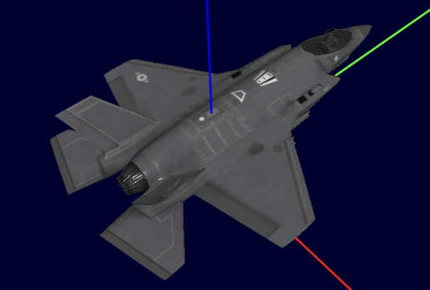
For example, Figure 1, “A 3D icon with its local coordinate system with transparency turned off. (X-Axis=red, Y-axis=green and Z-axis=blue)” shows a mesh that you want to place somewhere in the world.

As you can see in our example the plane has a hole where the cockpit should be.
This is because this mesh uses transparent textures.
To ensure that transparent textures are well handled you should set the transparency flag of the Icon3DStyle to true.
|
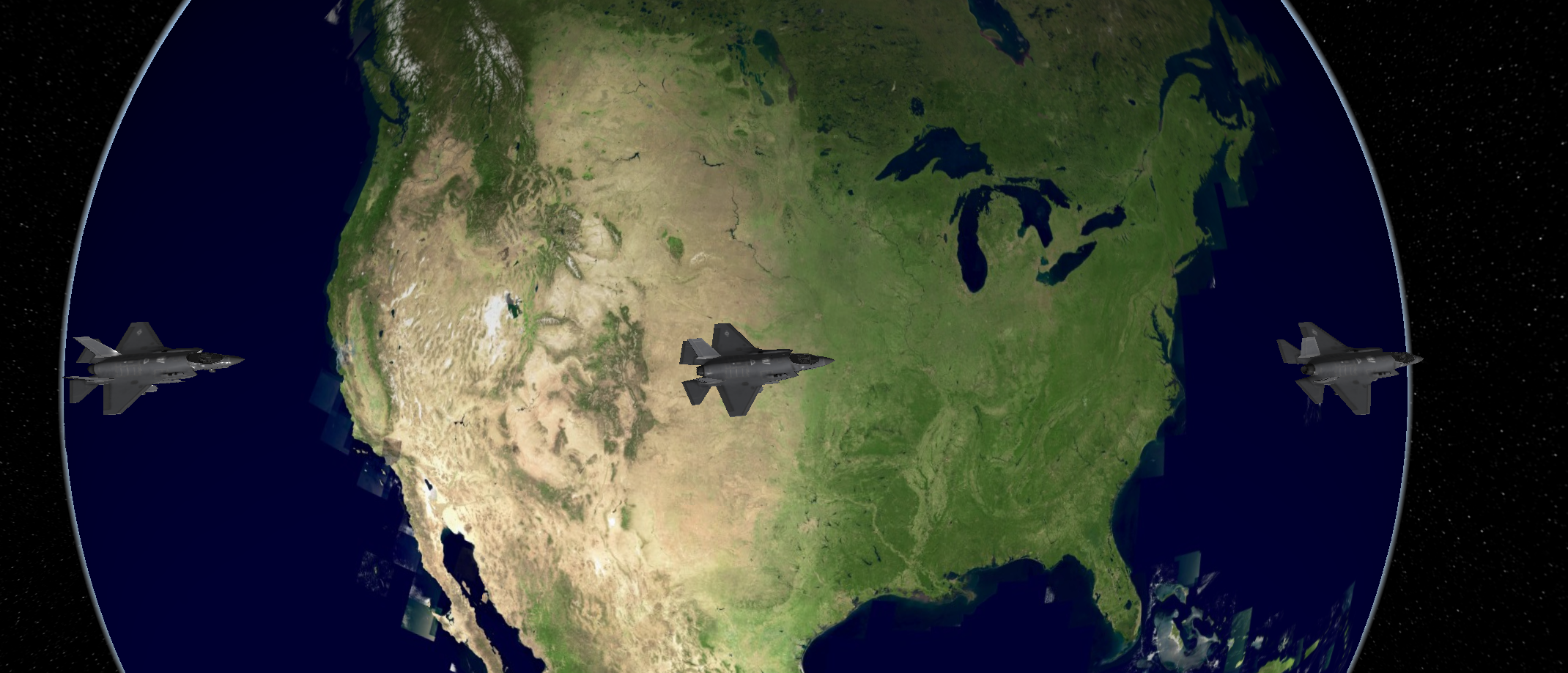
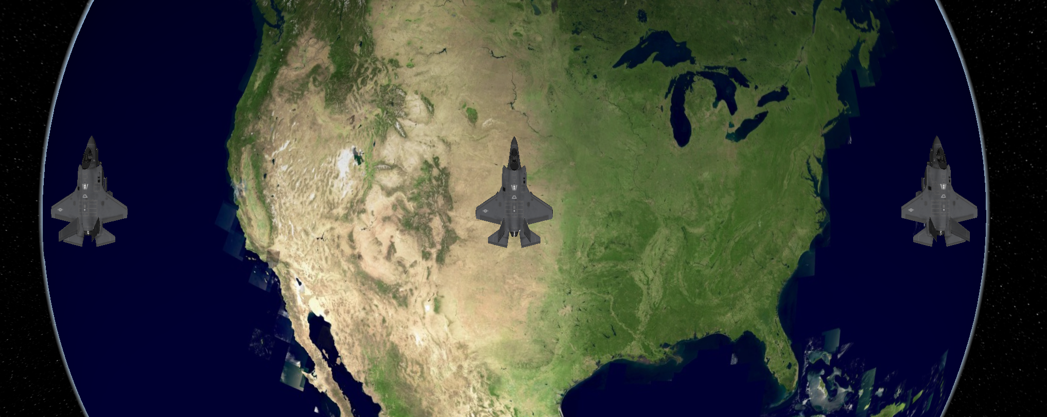
LuciadRIA places the mesh in the world at the location of the feature that you are styling, as in Figure 3, “Three icons, sharing the same mesh, placed in the world”. They share the same style so their orientation is the same. They all point in a certain direction. It depends on both the local and global coordinate system what direction that is.
Rotating the icon in its local reference
If you want to change the direction of an icon, you can specify a rotation property on Icon3DStyle.
As a result, LuciadRIA applies the specified rotation to the mesh in its local coordinate system before it places it in the
world.
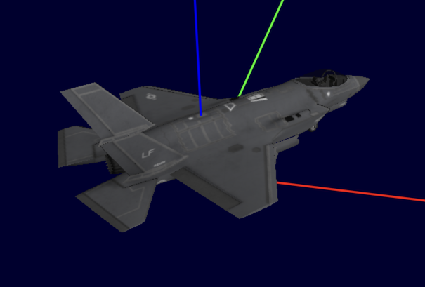
For example Figure 4, “A rotated 3D icon in its local coordinate system (X-Axis=red, Y-axis=green and Z-axis=blue).” shows a rotated version of the mesh in Figure 2, “A 3D icon with its local coordinate system with transparency turned on”.
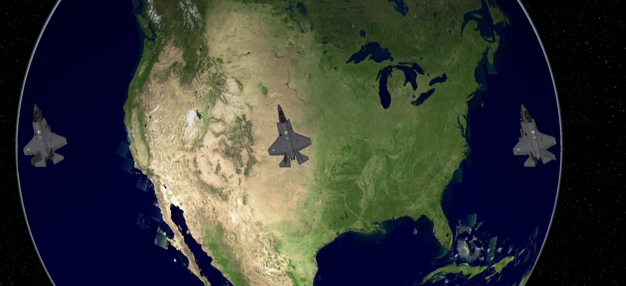
Using the rotation property, Figure 5, “Rotated icons placed in the world” points the icons of Figure 3, “Three icons, sharing the same mesh, placed in the world” in a different direction.
Orienting the icon in the world
Technically, the options described so far are enough to place, scale, and orient your 3D icon in every possible way, but they are not always practical. For example, if you want to point all three icons in Figure 5, “Rotated icons placed in the world” to the north, you must calculate the correct rotation for each position. You need to do that because the appropriate amount of rotation for each icon depends on its location on the earth.
To make 3D icon positioning easier, LuciadRIA doesn’t just use the combination of the axes of the local and global coordinate
system to place icons in the world.
You can first orient each icon, using the orientation property of Icon3DStyle.
You can set heading, pitch, and roll values.
If you don’t specify any orientation, or if it has value 0, LuciadRIA applies a default orientation.
|
In the default orientation, the y-axis of the mesh points north, the x-axis points east, and the z-axis points up, perpendicular to the surface of the earth at that location. |
If you want the icons to face east for example, you specify a heading of 90 degrees. LuciadRIA calculates the heading clockwise from the north.
Figure 6, “Three icons sharing the default orientation” shows the result of specifying the default orientation for the icons of Figure 5, “Rotated icons placed in the world”.
Program: Configuring the style for a 3D icon shows, among other things, the usage of the orientation property.
samples/icons3d/StyleFactory.js)
return {
  meshUrl: "/sampledata/gltf/goldengate/golden_gate.gltf",
  rotation: {
    x: 0,
    y: 0,
    z: 180
  },
  orientation: {
    heading: 0
  },
  scale: {
    x: 1,
    y: 1,
    z: 1
  },
  legacyAxis: false
};
Once you have defined the rotation of a mesh for one icon, other icons using the same mesh orient themselves with the orientation property. You don’t need to change the rotation for other instances.
See the API documentation of Icon3DStyle, Simple3DMeshFactory and MeshFactory for more detail.
Taking advantage of physically based materials
Some glTF files contain material parameters that you can use for physically based rendering (PBR) of 3D models. Such PBR shading looks more realistic than the default diffuse shading. See the glTF specification for more information about the material parameters for PBR.
To use this type of shading, configure the PBRSettings of your style.
Note that you must configure the map with a light to make PBRSettings take effect.
You can control the PBR shading look with these properties:
-
directionalLighting: indicates whether to shade the model with the lighting of the map. -
lightIntensity: increase or decrease the effect of the lighting on the model. -
imageBasedLighting: indicates whether to shade the model with the reflection map. -
material: configures scale factors for the PBR shading model. You can change the metalness and roughness of the material.
|
You can also style glTF files that don’t have PBR data with |
See the API documentation of PBRSettings and EnvironmentMapEffect for more details.
Using videos as textures
If you create your mesh using the MeshFactory, you can decide to use a HTMLVideoElement as a texture.
The first step is to load the video.
function loadVideo(videoUrl: string): HTMLVideoElement {
  const video = document.createElement("video");
  video.autoplay = true;
  video.muted = true;
  video.loop = true;
  video.src = videoUrl;
  video.play();
  return video;
}
You can also add controls so that users can manage the playback of the video displayed on the mesh. For example, you can let users pause and unpause the video by pressing the letter p on the keyboard.
function addPlaybackControl(video: HTMLVideoElement) {
  document.addEventListener("keypress", (a) => {
    if (a.key === "p") {
      if (video.paused) {
        video.play();
      } else {
        video.pause();
      }
    }
  })
}
Then, when you create the mesh, use the video as the texture by passing it into the image field of the MeshCreateOptions.
const video = loadVideo(pathToVideo);
addPlaybackControl(video);
const positions = [
  0, 0, 1, // vertex 0
  0, 1, 0, // vertex 1
  0, 0, 0, // vertex 2
  0, 1, 1  // vertex 3
];
const indices = [
  0, 1, 2, // triangle 0-1-2
  0, 3, 1, // triangle 0-3-1
];
const texCoords = [
  0, 0, // mapped to vertex 0
  1, 1, // mapped to vertex 1
  0, 1, // mapped to vertex 2
  1, 0, // mapped to vertex 3
];
return create3DMesh(positions, indices, {
  image: video,
  texCoords: texCoords
});
|