Introduction
Sometimes, a BIM dataset contains more elements than you are interested in.
Typically, this problem arises when a CAD model erroneously contains a copy of a building element, that is located far away from the actual data. (This can be in the orders of magnitude of hundreds of kilometers.)
While the actual data is of course present in the dataset, the erroneous objects cause problems when converting the geometry to an OGC 3D Tiles dataset: because the bounds of the dataset do not match the actual area of interest, it is impossible to automatically create a good tile structure. This can result in poor quality and unresponsive behaviour of a client application that consumes the 3D Tiles.
|
If possible, it is always better to change the source data in the original (CAD) application. |
OGC Filter
If changing the source data is not possible, then you can create an XML file, containing an OGC filter that describes the area of interest as a BBOX element.
File name
-
The model decoders for BIM data will look for a
*.filter.xmlfile next to the dataset. -
Similar rules apply to the detection of model reference files:
-
the same prefix as the entry point dataset
-
the prefix
directory -
the parent folder name as prefix
-
|
As an example, if your dataset is called |
File content
The file must describe an XML encoded OGC Filter. Please refer to the OGC Filters documentation for the full reference information.
An area of interest filter can be defined by using an Envelope inside a BBOX element.
<?xml version='1.0' encoding='UTF-8'?>
<fes:Filter xmlns:fes="http://www.opengis.net/fes/2.0" xmlns:gml="http://www.opengis.net/gml/3.2"
        xsi:schemaLocation="http://www.opengis.net/fes/2.0 http://schemas.opengis.net/filter/2.0/filter.xsd http://www.w3.org/2001/XMLSchema http://www.w3.org/2001/XMLSchema.xsd http://www.opengis.net/gml/3.2 http://schemas.opengis.net/gml/3.2.1/base/gml.xsd ">
  <fes:BBOX>
    <gml:Envelope srsName="urn:ogc:def:crs:EPSG::4979">
      <gml:lowerCorner>50.86448490 4.66901090 45.00</gml:lowerCorner>
      <gml:upperCorner>50.86519135 4.66990819 70.00</gml:upperCorner>
    </gml:Envelope>
  </fes:BBOX>
</fes:Filter>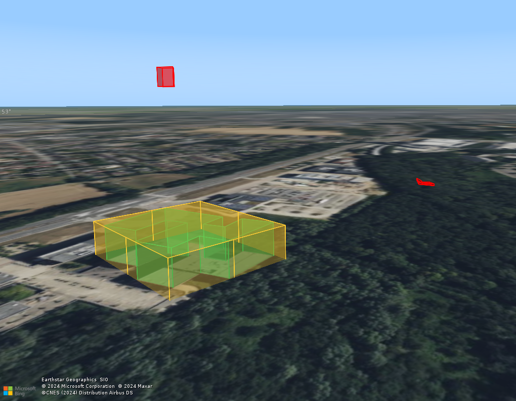
BBOX filter (yellow), effectively excluding the erroneous objects.
Important notes
-
If you provide a model reference (
srsNameattribute) that is defined in 3D (for instance, EPSG:4979), then the filter will be applied in 3D. If the reference is a 2D reference (for instance, EPSG:4326), then the height of the model elements will not be taken into account when filtering. -
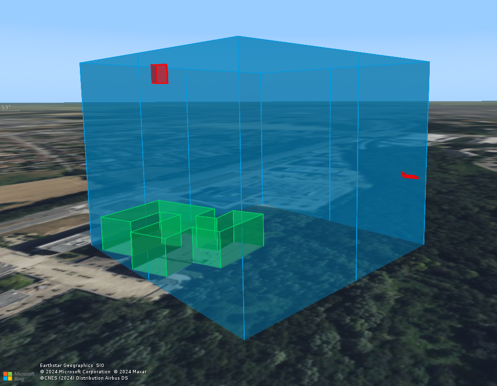
The filter uses the interacts with logic of the requested
BBOXwith the bounding box of each BIM element. This means that elements near the edges of theBBOXcan be retained even if the element itself doesn’t interact with it, as illustrated in the image below.

BBOX, but its bounding box does.