Introducing LuciadFusion
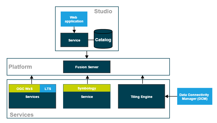
The main LuciadFusion components
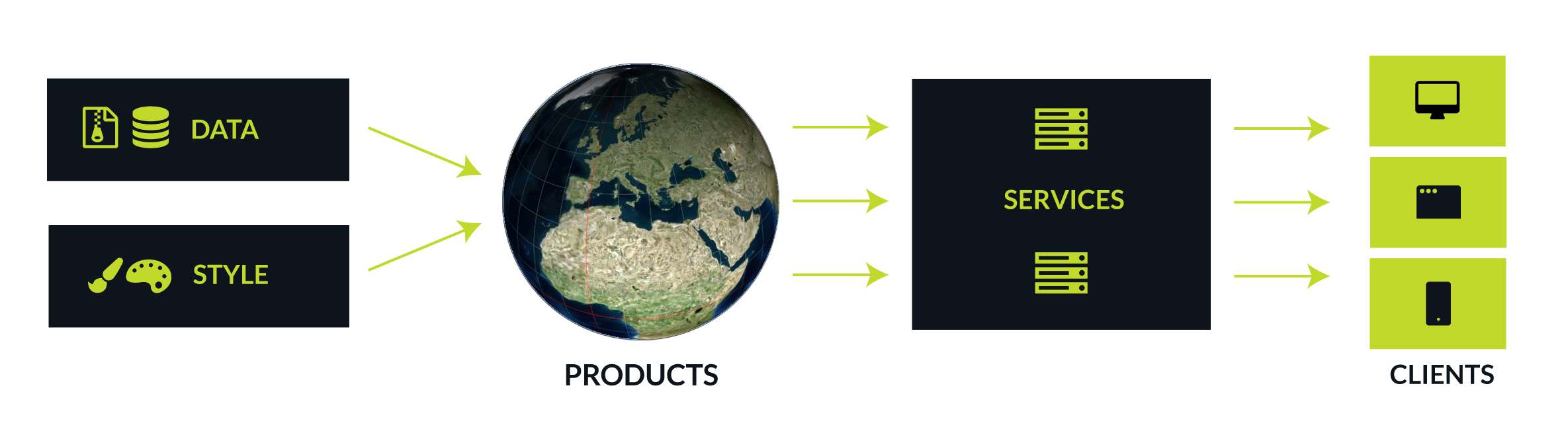
The main goal of LuciadFusion is to make managing and serving geospatial data easy. End users can easily access and readily visualize the data served by LuciadFusion in 2D and 3D on clients running LuciadLightspeed or other OGC-compatible applications.
The foundation of LuciadFusion is provided by the LuciadFusion Platform, a service application framework. It consists of the LuciadFusion Server and allows you to plug in custom services. It also offers data publication services out of the box, as well as other tools and services that facilitate data management and publication.
The LuciadFusion Studio
Data managers can turn to LuciadFusion Studio to manage geospatial data and serve it to client applications. LuciadFusion Studio is a web application that allows data managers to centralize their geospatial data in a catalog, manage and style their data, and publish the resulting products through the services hosted on the LuciadFusion Platform.
Managing data centrally
The LuciadFusion catalog describes the data or data series managed in LuciadFusion Studio. You get your data and data resources in LuciadFusion by uploading it, or by adding the location of the data as a data root, and letting LuciadFusion Studio discover the data by crawling the data root. LuciadFusion supports all data resources, including metadata and style files.
Once you have imported all data, LuciadFusion allows you to manage it centrally, create products from the data, and serve the data to client applications from services.
Publishing products
To serve your client applications an integral geospatial picture, you can combine several thematically related datasets into products, and publish that product through the LuciadFusion services. LuciadFusion products also allow you to style data differently according to client needs, by setting up several products that each combine the same data set with distinct style files.
LuciadFusion Platform Services
The LuciadFusion Platform hosts multiple services that allow you to publish your data to any geospatial application through various OGC and custom protocols:
- Serve data on-the-fly through OGC WxS services
-
Direct publication of data through OGC services, without fusing it upfront. Data can be published on a number of services defined by the Open Geospatial Consortium. The supported OGC service protocols are:
-
The OGC Web Map Service lets you publish data with styling applied.
-
The OGC Web Map Tiling Service lets you publish data with styling applied. The styled data is served in a tiled fashion.
-
The OGC Web Feature Service lets you retrieve vector data.
-
The OGC Web Coverage Service lets you retrieve raster data.
-
- Serve fused/pre-tiled data
-
The process of fusing data consists of converting data into a new data set organized in a hierarchical tile structure, often called a coverage. The OGC 3D Tiles services automatically fuses 3D point cloud and mesh data without any interaction. The Tiling Engine is a service that can fuse raster data on request. You can use the Data Connectivity Manager tool to configure the Tiling Engine.
| OGC 3D Tiles Service |
The OGC 3D Tiles service lets you publish a large amount of point cloud or mesh data using the 3D Tiles protocol. |
| Tiling Engine |
The Tiling Engine is a service that fuses source data to organize it in a hierarchical tile structure, a coverage. This optimizes access to the data, for the purpose of querying, visualization, and analysis. |
| Data Connectivity Manager (DCM) |
The DCM is a tool that allows you to connect to local or remote data sources, retrieve the data, fuse the data with the Tiling Engine, and store the fused data as coverages. |
| Tile Store |
A logical structure combining various coverages. You can use it in LuciadFusion V2016.1 and in the DCM, but not in the LuciadFusion Studio. |
| Luciad Tile Service(LTS) |
The Luciad Tile Service allows you to retrieve tiles that have been prepared using the Tiling Engine. |
- Serve dataset files through a web service
-
Provide direct access to the individual files of your datasets.
- Serve metadata through an OGC catalog service
-
Provide access to the metadata of your datasets and services.
- Serve Symbology through a service
-
The Symbology Service serves MS2525/APP6 icons. This is an optional service. The extent of your license determines whether you can use this service.
For each service type, except for the catalog and symbology services, you can create multiple instances, each hosting many products. You can set up two WMS services, for instance.
The LuciadFusion Platform is based on the well-known Spring framework for system and application development. Java developers familiar with the Spring framework can quickly familiarize themselves with the LuciadFusion Platform as well. They can also easily customize and extend the platform to suit the needs of their organization.
The LuciadFusion Platform also allows developers to add and remove services, customize services through configuration, and develop and plug in their own services, to perform additional data analysis for example.
The Data Connectivity Manager
The Data Connectivity Manager is a tool that allows users to connect to local or remote data sources, retrieve data, fuse the data, and store the fused data. This article describes how to run the Data Connectivity Manager and use its graphical user interface (GUI) out of the box.
Starting the Data Connectivity Manager
Before you can work with the Data Connectivity Manager you first need to:
-
Unzip the LuciadFusion distribution files
LuciadFusion_*.zipin a location of your choice.To unzip both files and install the license file at the same time, double-click the
install.jarfile, and start an automated installation. A LuciadFusion launcher window opens at the end of the installation process. If you use the automated installation, you can skip the next step.The result is one folder with
LuciadFusionand the LuciadFusion version number in its name, and a number of subfolders. -
If you are manually installing LuciadFusion, copy your LuciadFusion license files to the correct subfolders:
-
If you are installing a LuciadFusion version older than 2023.1:
-
Copy your standard LuciadFusion license file to the
licensesfolder. -
Copy your Data Connectivity Manager license file to the
Data_Connectivity_Manager/licensesfolder.
-
-
If you are installing a 2023.1 LuciadFusion or newer, copy your standard LuciadFusion license file to both the
licensesand theData_Connectivity_Manager/licensesfolders.
-
-
Start the default Data Server. You can start it in two ways:
-
From the LuciadFusion launcher (
start.jar), click the Fusion Server button. -
From the root directory of your LuciadFusion installation, click
FusionServer.bat(for Windows) orFusionServer.sh(for Linux and MacOS).
A command line or browser window opens, and displays the start-up process. The server is up and running when the message
Jetty started on port(s) 8081 (http/1.1)appears. -
-
Start the Data Connectivity Manager by clicking Data Connectivity Manager in the LuciadFusion launcher, or clicking
DataConnectivityManager.baton Windows orDataConnectivityManager.shon Linux and MacOS from the top LuciadFusion folder.The Data Connectivity Manager starts and the Tile Store connection dialog appears as shown in Figure 6, “The dialog box to open a Tile Store”. Enter the Uniform Resource Identifier (URI) of the Tile Store the Data Connectivity Manager should connect to, or select one from the list of stored favorites. Click OK to display the Data Connectivity Manager as in Figure 3, “The GUI of the Data Connectivity Manager”.
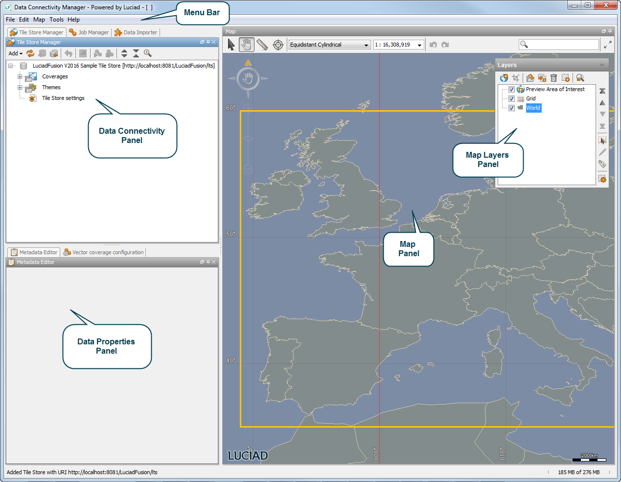
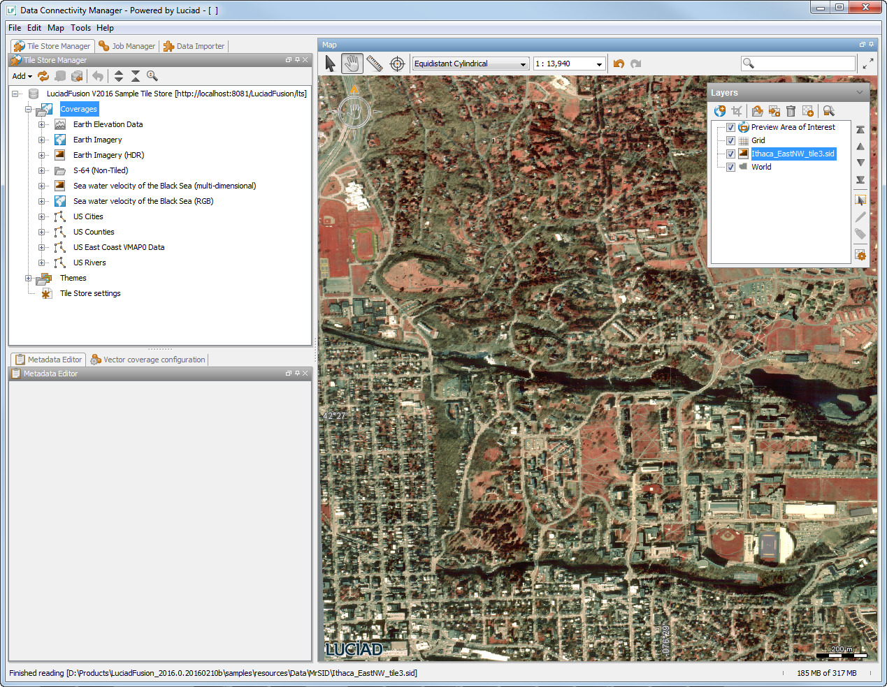
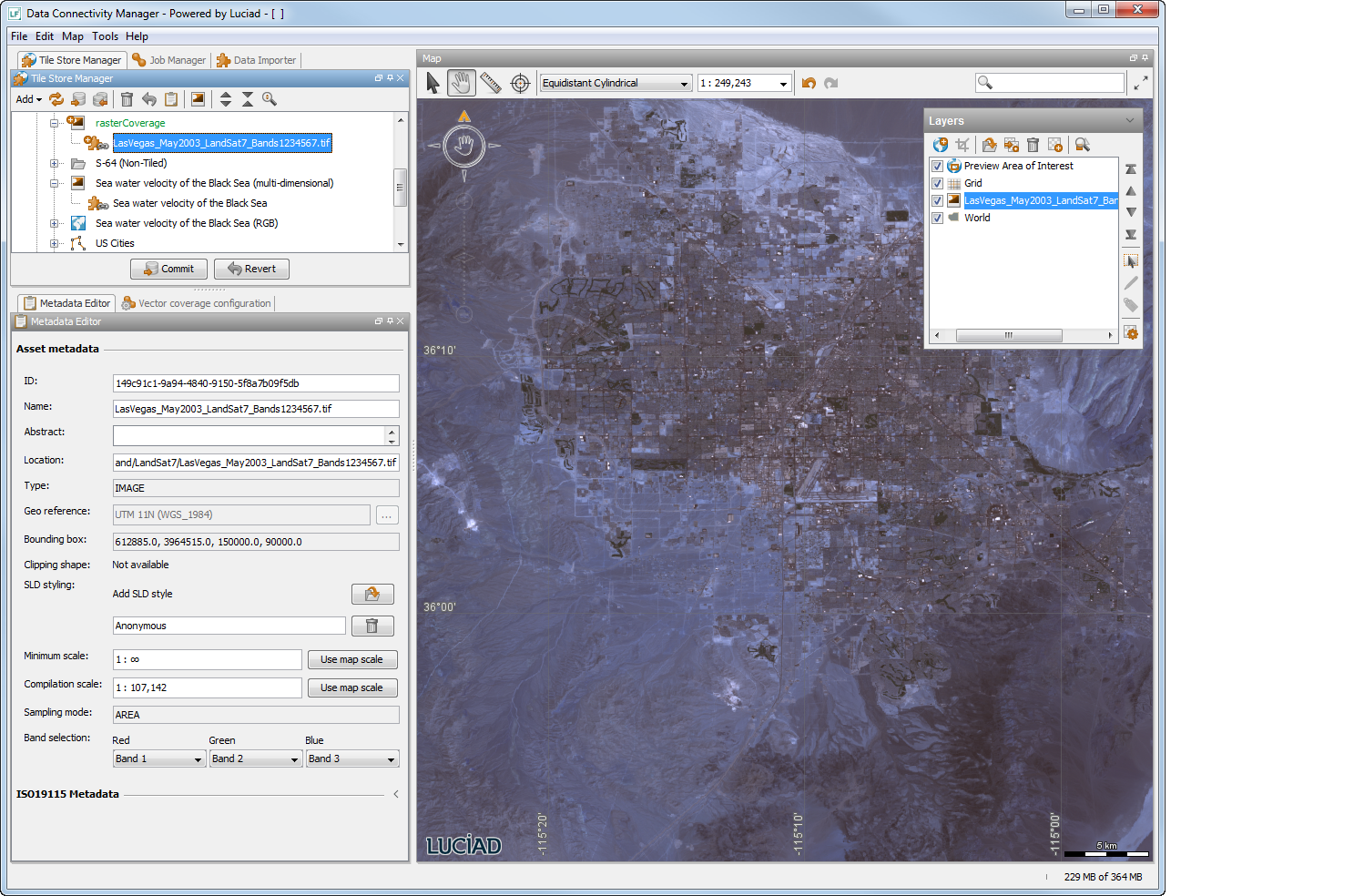
The GUI is based on Luciad’s application component Lucy, and contains the following basic elements:
-
The title bar
-
The menu bar
-
The Data Connectivity panel
-
The Map layers panel
-
The Data Properties panel
-
The Map panel
With the exception of the Data Connectivity and the Data Properties panel, all these elements are also part of the GUI for Lucy. For a complete description of the elements shared with Lucy and their usage, refer to the Lucy User’s Guide. This article focuses on the usage of the GUI elements that are specific to LuciadFusion.
The Data Connectivity panel
The Data Connectivity panel contains the following tabs:
-
Tile Store Manager: to manage resources
-
Job Manager: to manage fusion jobs
-
Data Importer: to import data into assets and coverages
You can enable or disable these tabs from the menu Tools| Fusion. The information and functionality provided by each of these tabs is listed below. A typical use case of the Data Connectivity Manager describes a typical use case of working with the Data Connectivity Manager.
The Tile Store Manager
The Tile Store Manager allows you to manage Tile Stores, coverages, assets, and themes. The icons in the header of the Tile Store Manager tab provide the following functionality:
-
 adds a Tile Store, coverage, or theme to the tree view
-
 refreshes a Tile Store view
-
 commits changes to a Tile Store on the server
-
 sets up data replication from another Tile Store
-
 removes a selected resource
-
 reverts a local change
-
 opens the tab with metadata for a selected coverage, asset, or theme
-
 creates a map layer from a resource
-
 starts fusion jobs for the selected coverages
-
 stops fusion jobs for the selected coverages
-
 configures fusion jobs for the selected coverages
-
 expands the collapsed tree view
-
 collapses the expanded tree view
-
 searches for specific resources
The Job Manager
The Job Manager allows you to manage fusion jobs. A fusion job is needed when assets have been added to a coverage and the coverage has been committed in the Tile Store. The Jobs tab shows the fusion jobs that have not run yet. The icons in the header of the Job Manager tab provide the following functionality:
-
starts the selected fusion jobs. Click on one or more jobs in the list to select the job(s).
-
stops the started fusion jobs. You can start the stopped job again later.
-
deletes the selected fusion jobs.
-
 reports the fatal or non-fatal errors that occurred during the selected fusion job.
The Data Importer
The Data Importer allows you to select data sets with multiple files from one data source. The Data Importer is particularly useful when loading batch files or huge repositories. Otherwise, you can load assets and create coverages as described in Loading new data. The icons in the header of the Data Importer tab provide the following functionality:
-
 allows you to browse for local or remote data.
-
 imports the selected data.
The Data Properties panel
The Data Properties allows you to display and edit metadata of a selected resource in the Metadata Editor.
See the next section for an explanation of the information and functionality provided by the Metadata Editor. A typical use case of the Data Connectivity Manager describes a typical use case of working with the Data Connectivity Manager.
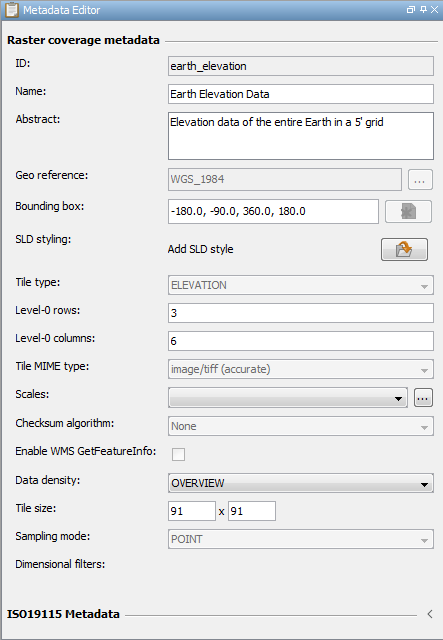
The Metadata Editor
The Metadata Editor tab displays metadata about a coverage, asset, or theme that is currently selected in the Tile Store Manager tab. Keep in mind that an asset refers to the original source data and the coverage to the fused data.
|
The changes you make in the editor are automatically applied to the metadata. The changes are only stored locally though,
so you need to commit them to the Tile Store. Use the |
|
Once you have committed changes for a resource, you can only edit the values for Name and Abstract. Edit any of the other metadata properties before you commit a new resource. See Changing committed coverages for more information about changing a committed resource. |
The icons in the header of the Metadata Editor tab provide the following functionality:
-
 makes a coverage compliant with the OGC WMTS GoogleMapsCompatible well-known scale set. The action will automatically adjust the georeference, bounding box, tile layout and tile size to match
the predefined GoogleMapsCompatible tile pyramid structure. This allows to publish the fused coverage via a OGC WMTS service.
makes a coverage compliant with the OGC WMTS GoogleMapsCompatible well-known scale set. The action will automatically adjust the georeference, bounding box, tile layout and tile size to match
the predefined GoogleMapsCompatible tile pyramid structure. This allows to publish the fused coverage via a OGC WMTS service.
Asset metadata editor
The Metadata Editor tab displays the following information for an asset:
-
ID: the LuciadFusion ID of the asset. Whenever an asset is added to a Tile Store, LuciadFusion gives the asset a unique ID. You can change the given ID by entering another value in the text box.
-
Name: the name of the asset as given by LuciadFusion. By default this is the file name without extension. You can change the name by entering another name in the text box.
-
Abstract: a short description of the asset. You can enter a new description or change a given description by entering a new text in the text box.
-
Location: the source location and the file name of the asset. For a multi-part asset, the Location box displays the text
Multiple locations, and the locations cannot be edited. -
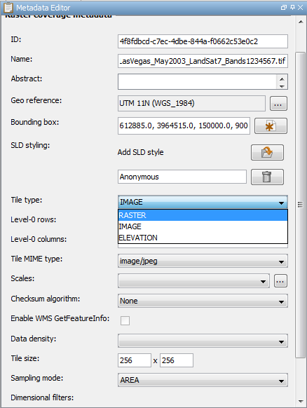
Type: the data type of the asset, this can be RASTER, IMAGE, or ELEVATION (height data).
-
Geo reference: the reference system of the asset. For a description and an overview of the possible reference systems refer to the Lucy User’s Guide.
-
Bounding box: the geographic area covered by the asset and given in the coordinates of the reference system of the asset.
-
Clipping shape: the availability for fusion of a more limited area clipped out of the full area covered by an asset. For more information, see Limiting the asset area to be fused.
-
SLD styling: allows you to select a Symbology Encoding (SE) file with an .sld extension that specifies the desired styling for the asset. The styling will be applied to the coverage asset served to WMS clients. If you define more than one styling by adding more than one SLD file, the WMS client users will be able to choose the styling they prefer for the data.
The term Symbology Encoding, or SE, refers to the description of the feature styling. The term Styled Layer Descriptor, or SLD, refers to the XML schema used to encode the styling descriptions only, but is frequently used interchangeably with SE. To learn more about OGC SE and SLD, and about using them for feature styling, see http://www.opengeospatial.org/standards/se. The LuciadLightspeed developer’s guide also offers information about OGC styling and filtering.
-
Minimum scale: indicates the minimum scale at which the asset should become visible, when fused to an image coverage. Normally you do not need to change this setting. You should only change it in specific cases where you’re not happy with the default settings and you want to override them manually. It can be used to tweak visibility of multilevel rasters.
-
Compilation scale: the scale the asset is compiled at, which is a measure for the asset’s data resolution. For raster assets, the compilation scale is derived from the pixel density, which expresses the number of pixels in the unit of the raster’s reference system. The concept of a compilation scale is equivalent to pixel density, but it is more intuitive and independent of any reference system.
-
Parameters: an optional set of parameters indicating the type of values stored in the raster data. For example, temperature or cloud coverage percentages. Note that this only applies to raster assets.
-
Sampling mode: the sampling mode of the asset, this can be AREA or POINT. Elevation data is typically point-sampled, image data typically area-sampled. This only applies to raster coverages.
-
Band selection: select a corresponding color channel for the bands in a multi-band asset. As a result, image coverages will preserve only the selected bands as red, green, or blue color information. In raster coverages, however, all bands will be preserved, along with the color mapping of three of those bands for visualization purposes. For more information, see Fusing multi-band data.
-
ISO 19115 Metadata: the available features or a list of all features. Select Available features to see only the features for which a value is available. Select All features to see all features, even if no value is available.
Coverage metadata editor
The Metadata Editor tab displays the following information for a coverage:
-
ID: the LuciadFusion ID of the coverage. LuciadFusion gives the coverage a unique ID if you don’t specify it when creating the coverage.
-
Name: the current name of the coverage. You can change the name by entering another name in the text box.
-
Abstract: a short description of the coverage. You can enter a new description or change a given description by entering a new text in the text box.
-
Type: the data type of the coverage. This can be RASTER, IMAGE, or ELEVATION (height data).
-
Geo reference: the reference system of the coverage. For a description and an overview of the possible reference systems refer to the Lucy User’s Guide.
-
Bounding box: the geographic area covered by the coverage, given in the coordinates of the reference system of the coverage.
-
SLD styling: allows you to select a Symbology Encoding (SE) file with an .sld extension that specifies the desired styling for the coverage. The styling will be applied to the coverage served to WMS clients. If you define more than one styling by adding more than one SLD file, the WMS client users will be able to choose the styling they prefer for the data.
-
Level-0 rows: specifies the tile layout by indicating the number of rows of the least detailed tile level of the coverage.
-
Level-0 columns: specifies the tile layout of the number of columns of the least detailed tile level of the coverage.
-
Tile MIME type: identification for the content type of the fused data (the tiles) based on the Multi-Purpose Internet Mail Extensions (MIME) protocol.
-
Scales: the scales to use for visualizing this coverage. By default, the scales are chosen so that for raster data, a pixel in the coverage data corresponds to a pixel on the screen (no resampling). They are a metadata concept for the (visualization) client, but they are not used to limit the visible range of data when the coverage is fused. Snapping to scales with CTRL-zoom uses these scales to snap to.
-
Checksum algorithm: the name of the message digest algorithm selected for checksumming the individual tiles in a coverage (optional). Checksums are stored locally with the tiles at the client side, where you can use them for coverage consistency checking if you want to.
-
Data density: a rendering hint which affects how the coverage is rendered in 3D.
DETAIL hints to load more detailed tiles in the foreground, at the expense of detail towards the horizon. You should use DETAIL for small features such as streets and buildings. OVERVIEW hints to load a more homogeneously detailed set of tiles, at the expense of detail in the foreground. You should use OVERVIEW for large features such as countries.
-
Tile size: the size of each tile in pixels. This only applies to raster coverages.
-
Parameters: the parameters for this coverage. It combines the U- and V- components of the wind variable in weather data in a single coverage, and also combines unrelated variables such as temperature and pressure in a coverage. If you are fusing to a
RASTERcoverage, this concept is replaced with band semantics. -
Sampling mode: the sampling mode of the coverage, this can be POINT or AREA. Elevation data is typically point-sampled, image data typically area-sampled. This only applies to raster coverages.
-
Dimensional filters: when you are fusing multi-dimensional data, you can select the range of preserve for each dimension. The list contains all the possible dimensions and their values provided by the assets. When the coverage type is RASTER, all possible values for all dimensions are selected by default, meaning the coverage will preserve all the multi-dimensional information of the source data. You can multi-select a subset of values to reduce the number of possible combinations. When the coverage type is IMAGE, only a single combination of values can be selected.
-
Maximum level: the maximum (most-detailed) level of the coverage. For raster coverages, the maximum level is also automatically determined based on the compilation scale of the assets.
-
ISO 19115 Metadata: the available features or a list of all features. Select Available features to see only the features for which a value is available. Select All features to see all features, even if no value is available.
-
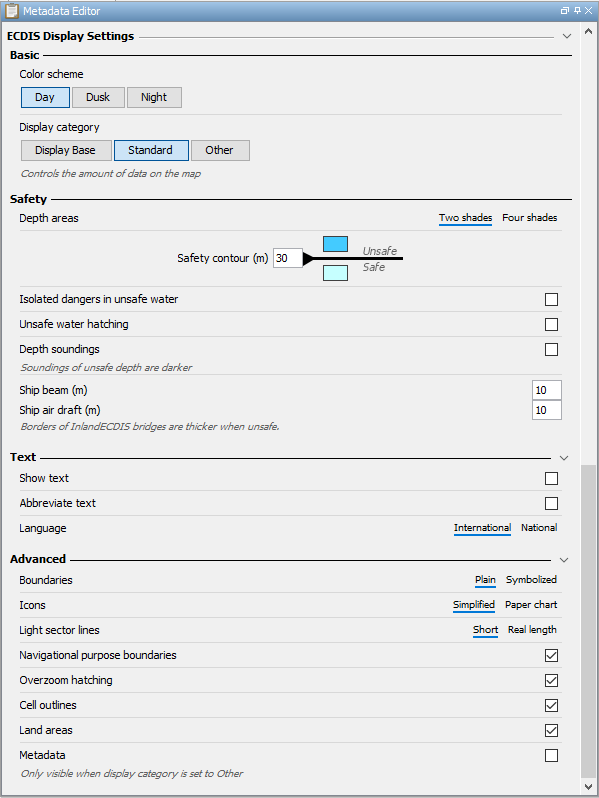
ECDIS Display Settings: only visible if the coverage contains ECDIS data. The display settings allow you to change the styling of the ECDIS data on the map. For more information about fusing ECDIS data and the ECDIS display settings, see Fusing ECDIS data.
Theme metadata editor
The Metadata Editor tab displays the following information for a theme:
-
ID: the name of the theme as given by the user when it was created.
-
Name: the current name of the theme. You can change the name by entering another name in the text box.
-
Abstract: a short description of the theme. You can enter a new description or change a given description by entering a new text in the text box.
-
Keywords: one or more keywords that you can use to identify the theme, separated by a comma.
-
ISO 19115 Metadata: the available features or a list of all features.
A typical use case of the Data Connectivity Manager
This section describes a typical use case of the Data Connectivity Manager which includes the following steps:
-
Connect to a Data Server to retrieve and open an existing Tile Store
-
Load data from other data sources and visualize the loaded data
-
Add the loaded data to the existing Tile Store
-
Run a fusion job to populate the coverage based on the data sources
Note that this is a sample scenario. There are many other use cases, for example using the Data Connectivity Manager to create a new Tile Store from scratch, as described in Creating a new Tile Store.
Opening a Tile Store
The first step of the sample scenario is connecting to a Data Server and opening a Tile Store from the server.
When the DCM starts up, the Tile Store connection dialog allows you to open or connect to an existing Tile Store on a Data Server.
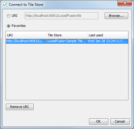
If you wish to connect to a different Tile Store at a later time, click the Cancel button. In the DCM, click on the Add icon in the Tile Store Manager header. Select Tile Store from the drop-down menu to bring up the Tile Store connection dialog.
The Favorites section shows the Tile Stores that have already been opened once before. If the Favorites section does not list the Tile Store that you want to open, you can enter the URI of the Data Server in the URI box. For example, the URI of the default Data Server is: http://localhost:8081/LuciadFusion/lts. By default, this Tile Store is available in the Favorites section already. Select the Tile Store and click on the OK button to open the Tile Store and add it to the Tile Stores tab.
|
Make sure that the Data Server is up and running as described in Starting the Data Connectivity Manager. |
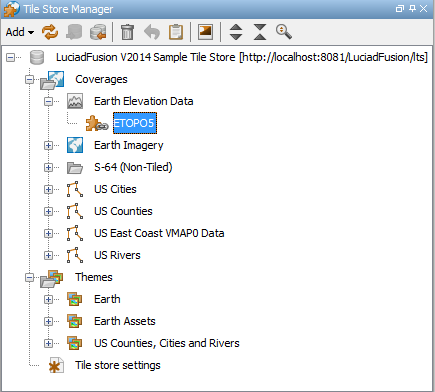
To see the resources that are contained in the Tile Store tree, click the + expanding icons next to the Tile Store name and the Coverages and Themes folders. Similarly, to see the resources that are part of a coverage or theme, click the + icon next to the name of a coverage or theme. Figure 7, “The opened Tile Store with its resources” shows the Tile Store tab with the opened Tile Store and its resources.
Visualizing resources
To visualize a resource in the Map panel, select the resource and click on the icon. A layer is created for the resource and is added to the Map layers panel. Double-click on the layer to show the coverage
on the map as shown in Figure 8, “The earth elevation layer visualized on the map”.
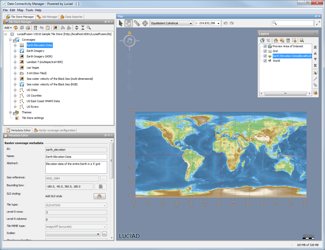
The layer is by default visualized in a 2D map but you can also visualize the layer in a 3D map. In the menu bar of the Data
Connectivity Manager, select File| New| 3D Map. A 3D map opens and the Map layers panel changes to the contents of the 3D map. To copy layers from the 2D map to the 3D
map, select the ![]() icon in the tool bar of the 3D layer control. Select layers from the dialog box that appears and click on the OK button to
add the layers to the 3D map. The added layers appear in the 3D Map layers panel. Double-click on a layer to visualize it
on the map. For more information for working with 3D maps, refer to the Lucy User’s Guide.
icon in the tool bar of the 3D layer control. Select layers from the dialog box that appears and click on the OK button to
add the layers to the 3D map. The added layers appear in the 3D Map layers panel. Double-click on a layer to visualize it
on the map. For more information for working with 3D maps, refer to the Lucy User’s Guide.
Non-tiled coverages cannot be visualized, but their assets can, as long as the asset’s location is a valid path for the DCM.
Loading new data
The Data Connectivity Manager is typically used to open data (assets) from different sources and fuse the retrieved data into a new or existing Tile Store. To load new assets, use the File| Open menu item. The Open dialog box allows you to select the files containing the assets you want to load. Click on Open to add the files to the Map layers panel.
If you want to load tile set data from a Web Map Tile Service (WMTS) service, use the File| Connect To… menu item, and enter the URL of the WMTS web service in the Connect To… dialog. If a Choose a format dialog opens, select the WMTS Client option. Subsequently, the WMTS Client dialog allows you to select one or more of the available WMTS layers. The selected WMTS layers are added to the Map Layers
panel.
Table 1, “Default supported file formats” in Appendix A, Supported formats shows the data formats and corresponding file extensions that LuciadFusion supports by default.
|
A file must have georeference information associated with it. This information can be available in the file itself or in an additional file. If a data file is loaded with an unknown georeference system (for example a .dgn file without a .ref file), a dialog pops up in which you need to select or define the georeference system as described in Section 5.4 of the Lucy User’s Guide. Select the Auto save check box in the bottom left corner of the dialog box so that the defined georeference system is saved together with the data file. The reference file gets the same name as the data file and the extension .ref. When the data file is opened afterwards, the reference file is opened as well. |
The file Ithaca_EastNW_tile3.sid is loaded from the folder \ samples\ resources\ Data\ MrSID. A layer is created for the loaded file and is added to the Map layers panel.
After double-clicking on the layer, the data is displayed in the view as shown in Figure 9, “The file Ithaca_EastNW_tile3.sid visualized on the map”. You can add the data to a coverage to the Tile Store as described in Adding data to a Tile Store.
Ithaca_EastNW_tile3.sid visualized on the map
Importing multiple files
The File| Open menu item is typically used to retrieve single source files. In some cases you might want to load multiple source files and put these in one coverage. For example, one satellite image can consist of hundreds of separate files. For this purpose you can use the Data Importer.
Click on the Data Importer tab or select Tools| Fusion| Data Importer. Click on the icon to open a dialog box that allows you to browse for assets. Click on Open in the dialog box to add the location to the tree in the Data Importer tab. You can search for specific files by entering
a file name and/or extension in the Filter box as illustrated in Figure 10, “Using the Data Importer filter to search for *.dat files”. You can use the wildcard * to broaden your search. Table 1, “Default supported file formats” shows the file formats and corresponding file extensions that LuciadFusion supports by default.
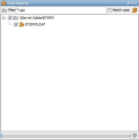
*.dat files
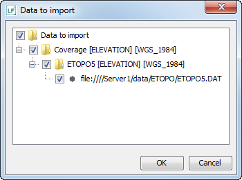
To add the files to the opened Tile Store, select the files and click on the icon next to the Filter box. The Data Import dialog box appears as shown in Figure 11, “The Data Import dialog box”. Click on OK to import the data. New coverages are added to the Coverages folder.
The Data Importer automatically groups the selected files into one or more multi-part assets such that similar files are part of the same asset. The data type and the geographic reference of the files have to be the same.
The Data Importer also automatically creates a coverage for the imported data. If the data has different types, different coverages are created.
|
The Data Importer can only be used for files that already have associated georeference information. If the georeference information is not yet available for a file, please use the regular File | Open menu item to load that file and choose the georeference information in the resulting dialog as described above. |
Finding places on the map
The search box in the map tool bar allows you to find places on the map. You can enter:
-
Coordinates: decimal coordinates or latitude/longitude coordinates.
-
Place names: country, city and landmark names.
-
Data properties: terms that possibly match the properties of the data loaded on your map.
The DCM uses search services to retrieve matches for the search terms you enter. If multiple matches are found, you can select the right match from a drop-down menu.
Press Enter, and the map will automatically fit to the area with the selected search result. The exact location is indicated with a placemarker. If the search result belongs to the data loaded on the map, the appropriate data object is selected on the map.
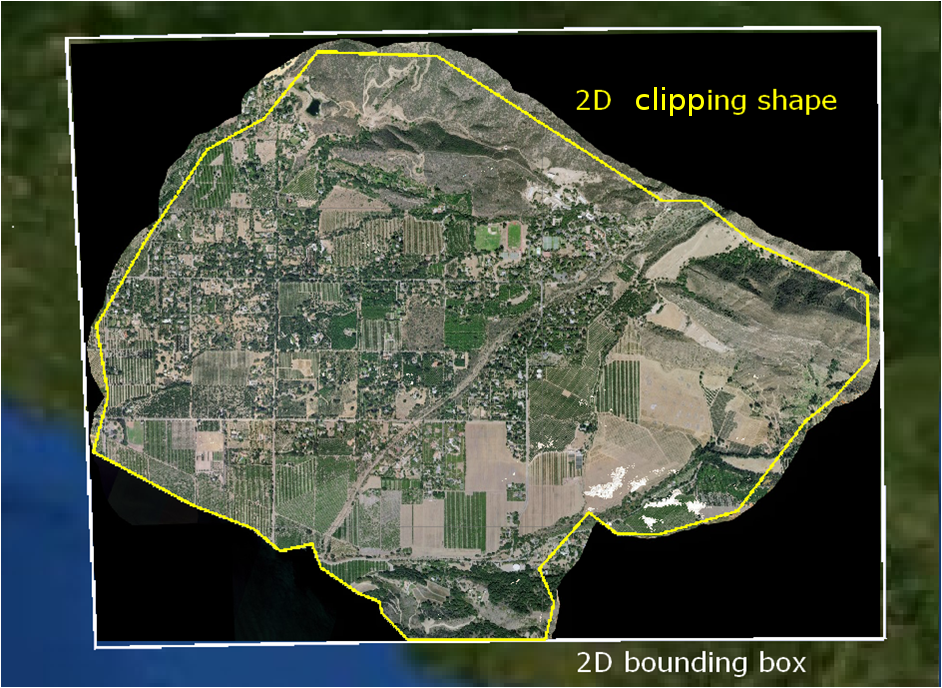
Limiting the asset area to be fused
In some cases, an asset may cover an area that you do not need or want to fuse entirely. You can limit the area to be fused by adding a clipping shape to the asset. Figure 12, “The difference between a bounding box and a clipping shape” shows an example: the bounding box shows the area covered by the asset, and the clipping shape represents the area that will be fused.
You can add a clipping shape to a new asset as follows:
-
Display the asset on the map as described in Visualizing resources.
-
Activate the drawing tool by selecting Map| Drawing bar. The Drawing bar is added below the map and a Drawing layer is added to the Map layers panel.
-
Select the shape that you want to draw. You can create a polyline, a polygon, or a rectangle by clicking on their corresponding button on the Drawing toolbar. To create a more advanced shape, click on the Shape button and select a shape from the pop-up list.
-
Draw the selected shape on the map using the mouse. Use the left mouse button to add points to the shape and move the mouse to determine the size of the shape. Double-click the final point to complete the shape.
-
Add the created shape to the asset by selecting the shape on the map and choosing the action
 in the Map Layers panel. Choose the destination asset in the dialog box that appears and click on OK.
The Tile Store panel shows a icon next to the asset with the bounding shape. In order to fuse the bounded asset and visualize it on the map, you first
have to add the asset to a coverage as described in Adding data to a Tile Store.
|
Note that you can only add a bounding shape to an asset if the shape is a Shape file or Drawing file. |
Adding data to a Tile Store
The default Tile Store contains the following coverages:
-
Earth Elevation: a coverage of the type ELEVATION containing the ETOPO5 asset.
-
Earth Imagery: a coverage of the type IMAGE that contains the blue marble GeoTIFF asset.
In a typical use case, data is retrieved from multiple sources and added to new or existing coverages. In some cases, the asset is in a Tile Store already, and you can add the asset directly from one coverage to another in the Tile Store Manager. If the loaded data is not in a Tile Store yet, you can add the data to a coverage from the Map layers panel.
To add data, consider whether the data is available in a coverage or not:
-
The data is already available as assets in a coverage. Add it to another coverage in the Tile Store Manager panel by:
-
Dragging and dropping the assets from one coverage to another
-
Right-clicking the selected assets and selecting the menu item Add to coverage
-
-
The data is in a map layer and must be added as a new asset. Add it from the Map layers panel by:
-
Dragging and dropping the selected layers to the Tile Store node or the coverages folder in the Tile Store Manager panel. New coverages will be created for the dragged layers.
-
Dragging and dropping the selected layers to an existing coverage in the Tile Store Manager panel. The layer is added to the coverage if possible.
-
Selecting one or more layers and clicking the
 icon. A dialog box will show the possible destination coverages. Select the destination coverage by clicking the corresponding
check box and clicking the OK button. An asset is created for the layer and added to the coverage. You can also automatically
create new coverages from this dialog box by clicking the Add to new coverage button.
icon. A dialog box will show the possible destination coverages. Select the destination coverage by clicking the corresponding
check box and clicking the OK button. An asset is created for the layer and added to the coverage. You can also automatically
create new coverages from this dialog box by clicking the Add to new coverage button.
-
Right-clicking on the selected layers and selecting the menu item Add to coverage. The Destination coverages dialog box lets you select a coverage or create a new one.
-
-
The data is in multiple files. Add the files in bulk with the Data Importer. See Importing multiple files for more details.
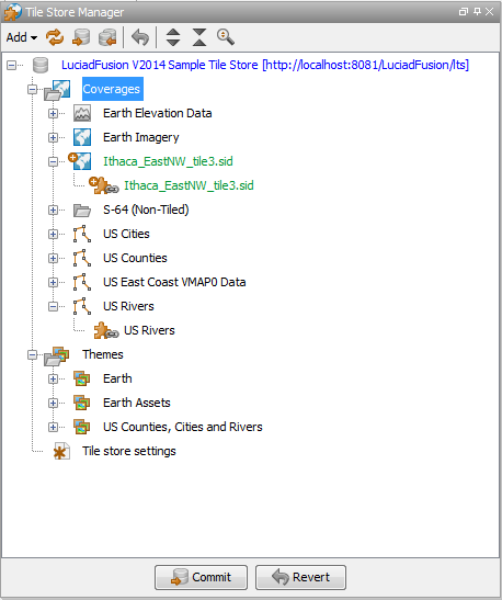
In the sample scenario, the layer that contains the file Ithaca_EastNW_tile3.sid is added a new coverage. The Tile Store tree colors blue in the locations with uncommitted changes. The new data itself is
indicated in green. To commit the changes you need to use the Commit button or icon as described in Committing changes to the Tile Store. Figure 13, “The Ithaca data added to the Tile Store” shows the Tile Store Manager tab with the new Ithaca data.
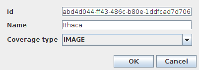
You can also create a new, empty coverage. Select the Coverages folder, click on the icon, and then select Coverage from the drop-down list. A dialog box appears as shown in Figure 14, “The dialog box for creating a new, empty coverage”. You can change the given ID for the coverage if desired, provide a name for the new coverage (Ithaca), and select the coverage
type (IMAGE). Click on the OK button to create the coverage.
This coverage is empty.
Ordering assets in a coverage
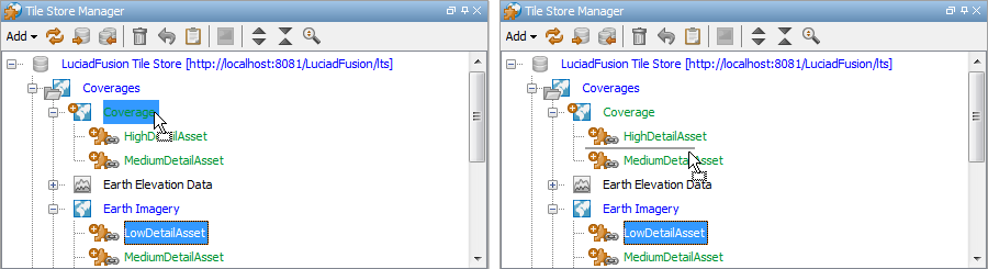
The order of assets in a coverage defines the visibility of the assets in the target coverage. Assets high in the list will be fused on top of the lower ones. As long as they have not been committed, it is possible to change the order of the assets in a coverage by dragging and dropping them. Assets cannot be dragged below already committed ones.
When assets are added to a coverage, they are generally inserted according to their natural order defined by their compilation scale, so that the most detailed assets are fused on top of the less detailed ones. The one exception is when an asset is dragged at a specific position under a coverage node. In that case, the asset will be inserted at that exact position.
Figure 15, “Dragging an asset on a coverage will insert it according to its natural order (left), while dragging it under a coverage node will insert it at the mouse pointer, in between assets (right).” illustrates the difference in semantics between dragging an asset on a coverage node and dragging it under a coverage node.
|
To restore the order of the assets in a coverage to their natural order, you can multi-select all the assets and drop them on the coverage again. |
Configuring coverages for use with WMTS
The LuciadFusion server allows exposing a fused raster coverage via the OGC Web Map Tile Service (WMTS) protocol.
WMTS also defines a limited list of well-known scale sets, with a fixed predefined tile pyramid structure. You can make a
new, uncommitted raster coverage compliant with the GoogleMapsCompatible scale set by clicking the button on the Metadata Editor tab. As a result, the georeference, the bounding box, the tile layout and tile size will match
the GoogleMapsCompatible tile structure, as defined by WMTS. Note that this function is also only available as long as the
coverage has not been committed yet.
Adding a coverage to a theme
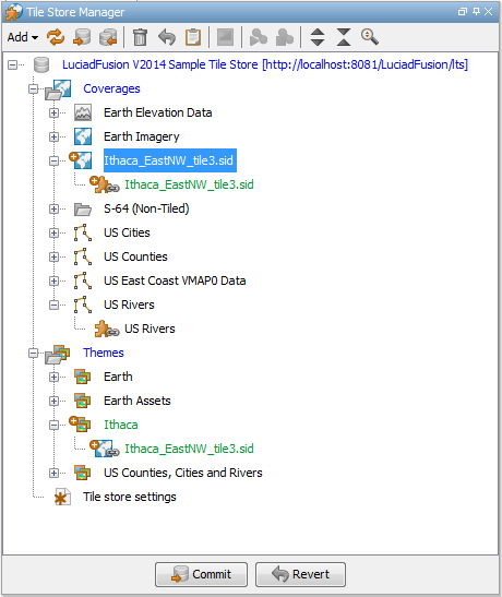
In the sample scenario, a new coverage has been created containing an asset that covers the area of Ithaca. For illustration
purposes, this scenario shows how to add the new coverage to a theme and save the theme in the Tile Store. In this case the
theme to which you can add the coverage does not exist yet. The first step is thus creating a theme. Select the Theme folder
and click on the icon, and then select Theme from the drop-down list. A dialog box appears that allows you to change the given ID and provide a name for the new theme
(Ithaca). Click on the OK button to create the theme. The new theme is added to the Themes folder.
Next, right-click the Ithaca coverage, select Add to theme from the options menu, and select the Ithaca theme in the Choose destination themes dialog. The coverage is added to the theme, as shown in Figure 16, “A newly created theme with the Ithaca coverage”
Committing changes to the Tile Store
Changes to a Tile Store that have not been committed yet to the actual Tile Store on the Data Server are indicated in one of the following colors:
-
Green: last made changes
-
Blue: contains one or more changes
-
Gray with strike through: deleted resource
Once a change has been made to a Tile Store you can commit the change immediately or you can wait and commit several changes
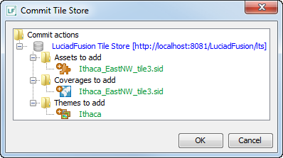
at once. To commit changes to the actual Tile Store on the Data Server, click on the Commit button or icon. A dialog box appears as shown in Figure 17, “The changes made to the Tile Store in the sample scenario”. Since no changes have been committed yet in the scenario, the dialog box shows all changes made to the Tile Store.
After the commit, the color indications will disappear to reflect the committed status of the resources. Move the mouse over the coverage name to display an information box and check the status of the committed change. To run the fusion job for a committed coverage, refer to Running a fusion job.
Changing committed coverages
You cannot change a coverage once it has been committed, aside from its name and its abstract. If you need to make changes to a committed coverage, you need to clone the coverage, and apply your changes in the clone. You can then proceed to commit and fuse the coverage clone.
To clone a coverage, right-click the coverage in the Tile Store Manager, and select the Clone menu item. The coverage clone is immediately added to the Tile Store Manager, and has the same name, with an additional copy
number, (1) for instance.
Running a fusion job
If a change to a coverage has been committed, a fusion job is required as indicated by the fusion (gear) icon. An additional information box with fusion details appears when you move the mouse over the coverage name.
By default, all fusion jobs are executed on the local machine. However, if you are currently connected to a Data Server that is also offering a Luciad Fusion Service (LFS), the Data Connectivity Manager will start any fusion jobs remotely on the Fusion Engine running on the Data Server.
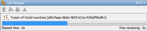
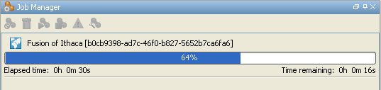
To start the fusion job, right-click on the coverage and select Start fusion job or click on the icon above the tree view. Open the Job Manager panel to view the progress of the fusion job. The progress bar shows the progress
of the fusion job in percentages. You can check the following details of the job:
-
The elapsed time in seconds
-
The estimated time remaining in seconds
Figure 18, “The running Ithaca fusion job” shows the running Ithaca fusion job.
To cancel the job, click on the  icon. Note that this action will delete the job.
To stop the job, click on the icon. You can start the stopped job later by clicking on the icon again. Note that you can even restart a stopped fusion job when the application is restarted.
Exporting coverages to a Tile Store
LuciadFusion allows you to export a coverage from one Tile Store to another. During such an export, LuciadFusion takes a copy of the fused coverage data, and inserts the copy into the other Tile Store. There is no need to commit and fuse the coverage again in the target Tile Store.
To export coverages from one Tile Store to another one:
-
Open both Tile Stores.
-
In the Tile Store manager, select the coverage from the source Tile Store and right-click it. Select the option Export coverage to Tile Store. A dialog box allows you to select the target Tile Store.
-
Click OK to export the coverage. An export job showing progress and remaining time will be visible in the Tile Store Manager panel.
Note that while the export is ongoing, you can already visualize the result on the target Tile Store by creating a map layer from the coverage.
Exporting coverages as OGC GeoPackage files
LuciadFusion allows you to export raster coverages from the Data Connectivity Manager, and save them in the OGC GeoPackage format.
GeoPackage is an OGC standard format for the storage of geospatial information, based on SQLite. It is lightweight, platform-independent, and designed to enhance interoperability between geospatial applications in all kinds of environments. For instance, you can export a LuciadFusion raster coverage as a GeoPackage file, and then use the coverage data on a mobile device.
To save a raster coverage in the GeoPackage format:
-
Right-click the raster coverage in the Tile Store Manager, and select the Create Map Layer option. The coverage is added as a layer in the Map Layers panel, and is displayed on the Map.
-
Go to File | Save as, select the raster coverage layer that you want to save, and click OK.
-
In the Files of type menu, select
GeoPackage (*.gpkg). -
Set the GeoPackage saving options:
-
In the Compression format drop-down menu, indicate whether you want to compress the data to a JPEG file or a PNG file.
-
Use the Quality slider to set the required quality of the image compression.
-
In the Cropping drop-down menu, indicate if you want to store all the data in the layer, or just the data currently visible on the map.
-
To store all data, select None.
-
To save just the data on the map, select Current Map Extent.
-
Select a Coordinate Reference System for your data from the CRS dropdown menu.
-
Click Save to save the raster layer.
Fusing raster data to a raster coverage
All default LuciadFusion input formats can be fused into raster coverages. This section focuses on the fusion of raster data into a raster coverage.
When you are fusing raster data, the pixel density of the assets defines their natural resolution. Raster coverages have a tile size, which, together with the coverage layout and bounding box, defines the resolution at the discrete levels of the tile pyramid.
Given a coverage’s bounding box, layout, and tile size, LuciadFusion chooses the maximum level (depth) of the tile pyramid so that its resolution is at least as good as the resolution of the most detailed asset. For raster coverages, the depth of the tile pyramid is adaptive, meaning that the depth of the tile pyramid is not necessarily uniform across the coverage’s bounding box. The tile pyramid will have more levels in areas which overlap with highly detailed assets.
You can choose to create raster coverages of the generic type RASTER, or of one of the specific types IMAGE or ELEVATION.
Selecting the right coverage type
The generic type RASTER is a supertype of types IMAGE or ELEVATION. If you select the RASTER type, the image processing API is used to fuse the source data, and you can preserve the band semantics of the source data.
To help you decide whether to select either the RASTER type, one of the other two raster coverage types, or even fusion to an IMAGE coverage, we list its advantages and limitations.
Choose the RASTER coverage type if you want to:
-
Preserve the band information of multi-band data, such as Landsat data. All the band information is preserved as a multi-band image.
-
Preserve the measurement band semantics and the measure type code of NetCDF data
-
Preserve the dimensional information in multi-dimensional data, such as NetCDF. All the dimensional information is preserved as separate pages of a multi-page TIFF.
-
Warp source data to the coverage’s geographic reference more accurately than with
IMAGEfusion. -
Handle any sample data type: 8-bit, 16-bit, 32-bit integer or 32-bit and 64-bit floating point (double).
-
Make optimal use of the image processing API offered by LuciadLightspeed for processing your decoded data further.
For more information about fusing multi-band and multi-dimensional data, see Fusing multi-dimensional data and multi-band data.
Generic RASTER fusion is more powerful than the other two raster coverage types. The other two types can still be useful to you if you have
fusion requirements do not match with the limitations of the RASTER coverage type:
-
Fusion speed is more important to you than accuracy. Generic
RASTERfusion is more accurate but slower than the other fusion types, especially when source data needs to be warped to fit the coverage’s geographic reference. -
You need to support additional detail.
RASTERcoverages do not support additional detail. You can only fuse a coverage in one shot. If you need to support additional detail, you must use theIMAGEorELEVATIONcoverage subtypes. For more information about additional detail, see Fusing additional detail. -
You need a compact tile format for elevation data. Generic
RASTERcoverages do not support a compact tile format for elevation data. For that, you need to use an elevation coverage with an "image/png" tile format. -
You want to use the legacy LuciadLightspeed raster or tile set API with the coverage data. When a
RASTERcoverage is decoded as a LuciadLightspeed model, it only obeys the image processing API according to the `has-an-image' paradigm.
Fusing additional detail
By default, assets in a coverage are ordered according to their pixel density. The most-detailed assets are on top of the less-detailed ones. As long as a coverage has not been committed, it is possible to manually re-order the assets through drag-and-drop. Once a coverage has been committed but has not been fused yet, you can no longer re-order the assets.
When a coverage has finished fusing, you can add assets to it again, but only on top of the already existing assets. You can then fuse the coverage again. This process is known as fusion of additional detail, sometimes also called incremental fusion. You can use it to fuse a low-resolution base layer first, and add a high-resolution imagery on top later on.
Aligning coverage rasters with asset rasters
Because LuciadFusion is intended for combining assets with heterogeneous geographic references and resolutions into a single coverage, the coverage’s rasters correspond to the different levels of detail, and often do not match exactly with the assets' rasters. LuciadFusion interpolates the input data to fit the rasters of the coverage.
If all assets have the same natural resolution and geographic reference, you can often eliminate interpolation at the most detailed level by aligning the coverage’s raster with the assets' rasters. Doing so will effectively preserve the original resolution and sample values of the input data at the most detailed level. Less detailed levels will still be interpolated. LuciadFusion does not perform this alignment automatically, but you can manually configure the coverage for this.
For example, suppose you want to fuse multiple raster assets with EPSG:4326 as the common geographic reference and a resolution of 1' x 1', aligned to the Earth’s longitude/latitude grid. The following coverage configuration will align the coverage’s raster at level 4:
-
Bounding box: -180°, -90°, 360° x 180°
-
Layout: 6 x 3 so that tiles at level 0 have bounding boxes of 60° x 60° (30° x 30° at level 1, 15° x 15° at level 2, 7.5° x 7.5° at level 3, 3.75° x 3.75° at level 4, and so on)
-
Tile size: 225 x 225 so that pixels at level 4 are exactly aligned to the input data raster of 1' x 1': 3.75 * 60 = 225
A tile size of 450 x 450 also results in an aligned raster, but at level 3 instead of level 4. There is always a mathematical solution, but sometimes the resulting tile size is impractically large.
Fusing multilevel raster data
Some raster formats, such as GeoTIFF, can have multiple levels of raster data which are structured in a multilevel raster. LuciadFusion automatically uses the rasters at the appropriate level to produce its own tile pyramid. When the level relationship of the multilevel source data is "overview", the levels are different representations of the same data, and LuciadFusion fuses them in a mutually exclusive way. This means that one level of source data will replace another in the fused coverage. When the level relationship of the multi-level source data is "stack", the levels are unrelated, and LuciadFusion fuses them as unrelated source data. This means that one level of source data may be fused "on top" of another one.
Some raster formats, such as CADRG or ECRG, can have multiple rasters which are not structured in a multilevel raster. This is semantically the same as a multilevel raster with level relationship "stack". LuciadFusion treats it as such: as unrelated source data.
Fusing tile set data to an image coverage
LuciadFusion allows you to fuse WMTS layers to image coverages. You achieve the best fusion result by fusing just the required WMTS layer to the image coverage, and not mixing in any other datasets. LuciadFusion automatically applies the most optimal settings for the fusion of a WMTS tile set to an image coverage: the DCM detects assets with a tile set structure, and configures the image coverage metadata accordingly.
Keep in mind that if you set one of the coverage parameters manually, your coverage structure may no longer match, and you may not be able to benefit from any tile set fusion optimizations.
Fusing multi-dimensional data and multi-band data
LuciadFusion allows you to fuse multi-dimensional and multi-band data, such as NetCDF or GRIB data, to raster coverages, and still preserve the multi-dimensional and multi-band nature of the source data. You can even filter the dimensional information by choosing to preserve only a subset of the dimensional information of the source data.
If you want to preserve all bands or dimensions of multi-band and multi-dimensional data, you need to select a RASTER coverage type. For more information about the available coverage types, see Selecting the right coverage type. However, you can still choose to fuse to an image coverage type if necessary.
About NetCDF
The NetCDF data format describes array-oriented scientific data. NetCDF scientific weather data is stored as gridded datasets. The types of measurement and the dimensional axes along which they are measured determine the structure of the datasets. The measurements are referred to as variables. Temperature, humidity, and cloud cover are all examples of variables. The dimensions of the measurements typically consist of the location coordinates of the measurement, the time of the measurement, and other parameters, such as the altitude at which the measurement was taken. For instance, atmospheric temperature can be measured at a specific location, but at multiple times and vertical positions. Wind data typically comes as two wind component variables, U and V.
These measurements result in a NetCDF temperature dataset, with measurement grids organized in spatial, temporal and vertical dimensions. By default, NetCDF allows multiple sets of variables in a single file, so one NetCDF file can contain both salinity and temperature measurements for example.
About multi-band data
Multi-band or multi-spectral images offer data captured on spectral bands other than the visible wavelengths of the electromagnetic spectrum, such as infrared and radar bands. Images captured on the infrared bands, for example, are extremely useful for visualizing and analyzing surface and soil features, such as vegetation, soil moisture levels, crop health and the presence of man-made structures in a natural area.
Fusing NetCDF or GRIB data to a raster coverage
To fuse a set of NetCDF or GRIB data, select the Raster coverage type when you are setting up the coverage.
LuciadFusion fuses the NetCDF or GRIB data to a raster coverage as follows:
-
Each variable is modeled as a separate coverage. If a dataset has two variables, such as temperature and pressure, they are fused into two distinct coverages.
-
Related variables, such as the wind U-component and the wind V-component, can be fused to a single raster coverage with two bands. The two bands in a wind coverage correspond to the U-component and the V-component, which is consistent with the source model.
-
Each variable can have a time dimension and a vertical dimension. Each possible combination of dimensional values of a variable corresponds to one page of a multi-page TIFF file. For example, if the data has 3 temperature values on the time axis and 4 temperature values on vertical axis, the resulting model has 3 x 4 = 12 different TIFF pages. For this reason, you can only select TIFF MIME types in the Tile MIME type field.
-
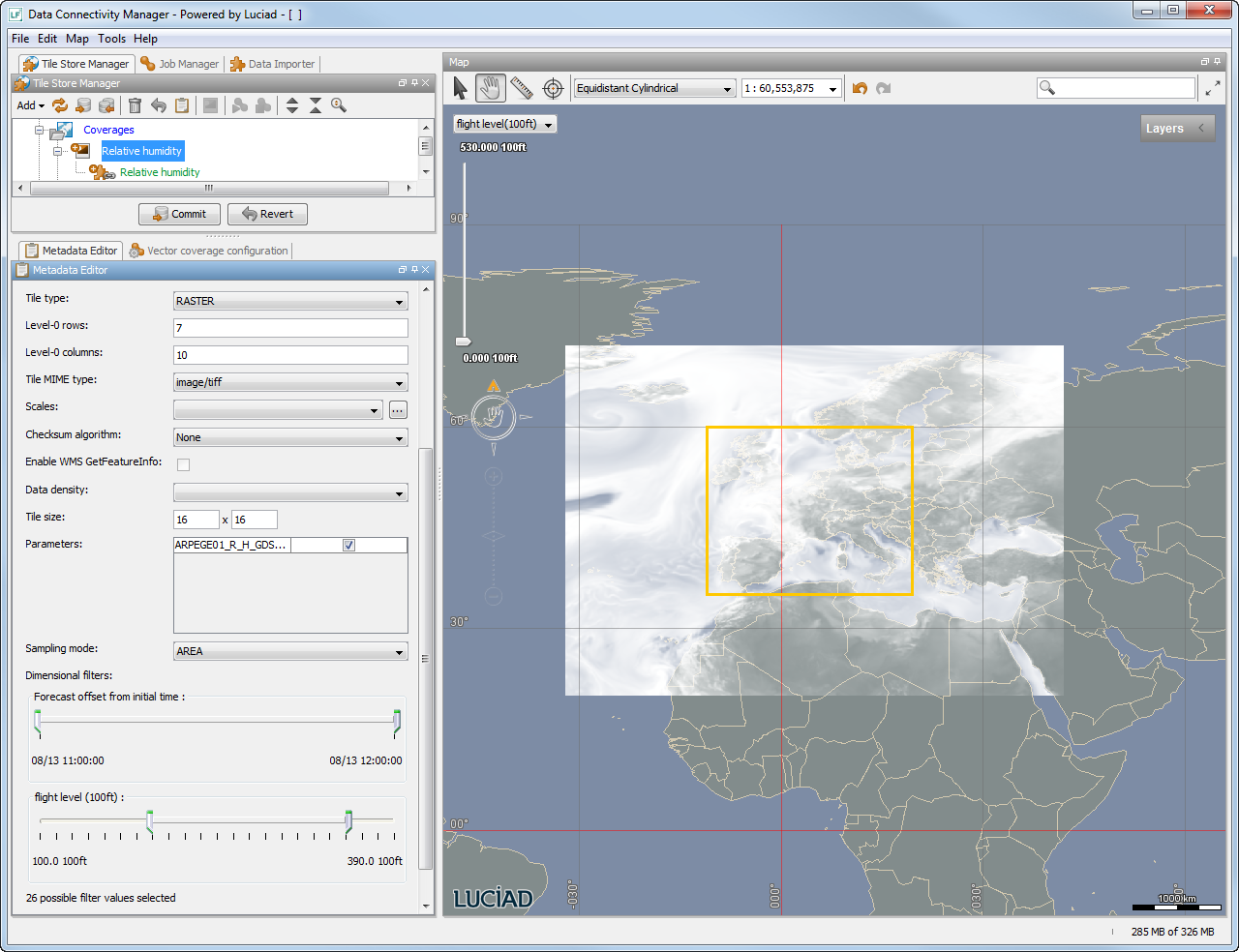
By default, a raster coverage preserves all the dimensional information, but you can filter it to preserve only a subset of the dimensional information. To select the information you want to preserve, go to the Dimensional filters panel in the coverage Metadata Editor. For each dimension, drag the sliders to match a suitable, narrower range of values. The number of possible filter values below the file is automatically updated to match your selection.
Because fusion as raster coverage preserves the multi-dimensional and multi-band nature of the NetCDF data, the decoded model for a raster coverage will be indistinguishable from the original NetCDF model. You can therefore treat it as a regular NetCDF model for most purposes such as painting, retrieving values, and so on.
Fusing NetCDF data to an image coverage
It is also possible to fuse NetCDF data to an image coverage.
Because an image coverage is uni-dimensional, you can only select a single combination of possible multi-dimensional values. The image tiles will be rendered for that combination only. You can select this combination using the Dimensional filters panel on the coverage Metadata Editor; you can filter the image coverage for a specific time and a specific vertical value to obtain an image and fuse that single image.
Even though the fusion of NetCDF data to a raster coverage offers more possibilities than the fusion to an image, you can still select an image or elevation coverage type for the following reasons:
-
You only need a single dimensional filter, and you want to save bandwidth. Preserving multi-dimensional data costs bandwidth, which is wasteful if you do not need it.
-
You want to offer the coverage as WMTS layer. The WMTS server does not support raster coverages yet. It only supports image coverages.
-
You want to use a compact tile format for elevation. Raster coverages do not support a compact format yet.
-
You need to be backward-compatible with older versions of LuciadFusion clients.
-
You need to add additional detail later.
Fusing multi-band data
You can fuse data consisting of multiple bands to either a raster coverage or an image coverage. If you want to preserve the bands after fusion, select the raster coverage type when you are setting a coverage for your multi-band assets.
Multi-band raster coverages preserve all available bands in the multi-band data set in the coverage. For instance, if you fuse 7-band satellite imagery, the 7 bands will still be available in the coverage for further processing and analysis. To choose what bands in the sets you want to visualize, you can map three of the bands to the Red, Green and Blue color channels in the Band selection drop-down menus of the asset Metadata Editor.
If you do not want to preserve the bands in a multi-band data sets, you can select an image coverage type. On the asset Metadata editor, you can select which three bands will be preserved as colors in the resulting coverage. Map the required three bands to color channels in the Band selection drop-down menus. All information about the other bands will be discarded during fusion.
Fusing GDAL data
It is possible to fuse raster data that is supported by the standard GDAL model decoder. You can fuse it to a raster, image, or elevation coverage. For example, you can fuse ERDAS Imagine data (*.img) using GDAL. Such raster data can be single-band or multi-band color data, or measurement data.
Fusing to a raster coverage
You can fuse GDAL data to a raster coverage. In this case, the multi-band semantics are preserved.
Fusing to an image coverage
When you fuse multi-band data to an image coverage, you are projecting the multi-band information onto RGB color space. Therefore, you need to define a filter as if you were visualizing the information: you can choose which bands you want to visualize as an RGB image on the Asset metadata editor. The resulting image coverage will contain RGB images.
Fusing ECDIS data
An Electronic Chart Display and Information System (ECDIS) is a computer-based navigation system which is used to visualize digital nautical data, as an alternative to paper nautical charts. Nautical data includes all information which may be of assistance for the safe navigation of vessels at sea and harbors, such as sea depth information, positions of buoys, lights, wrecks, and so on.
The International Hydrographic Organization (IHO) has published a number of publications that standardize the way how ENC data should be encoded, visualized and protected.
LuciadFusion offers support for the following ECDIS data types:
-
S-57 low-level data format
-
S-63 low-level data format, the encrypted form of S-57 data
-
Electronic Navigational Chart (ENC) product type, with its specific S-52 symbology
-
InlandECDIS (IENC) product type, with its specific symbology
-
Additional Military Layers (AML) product type, with its specific symbology
If you want to fuse ECDIS data, you have a number of different options, each with its specific benefits and limitations.
Fusing to an image coverage
The first option is to fuse to an image coverage (a raster coverage of type IMAGE). In this configuration, tiles are rasterized with a fixed default styling. The default styling can be configured in the
coverage metadata panel, and will only be shown when applicable, as in Figure 22, “The ECDIS display settings in the coverage metadata panel”. See the Lucy User’s Guide for a description of the fields in this panel.
Fusing to an image coverage has the following advantages and limitations:
-
[plusicon.png] The coverage supports the protocols LTS, WMS and WMTS with minimal overhead.
-
[minusicon.png] Dynamically changing the rendering style is not supported. The default rendering style is defined up front, and can no longer be changed afterwards.
-
[minusicon.png] WMS GetFeatureInfo is not supported.
-
[minusicon.png] ECDIS rendering is pixel-perfect only at the discrete map scales that correspond exactly to the native levels of the coverage. Rendering at other scales may result in rasterization artefacts.
Fusing and serving encrypted ECDIS data
LuciadFusion supports both the unencrypted S-57 format and the encrypted S-63 format as low-level ECDIS data formats. It will decrypt and encrypt S-63 data as needed while fusing and serving the data.
|
Before you load and fuse encrypted S-63 data, make sure that the cell permit files |
To decrypt the data, LuciadFusion uses a key based on the S-63 hardware ID, which is part of the LuciadFusion license. In the absence of a hardware ID, the official IHO hardware ID for S-63 test data will be used as a fallback.
The S-63 encryption standard requires that the persisted data is encrypted again, once it has been fused. To meet this requirement, LuciadFusion always automatically encrypts coverages that contain S-63 data, again by means of a key based on the S-63 hardware ID in the license.
Encrypted coverages are decrypted when they are visualized either on the client or on the server, depending on the protocol. If you do not have the correct hardware ID in your license on the system doing the visualization, the visualization will fail.
In general, you need to store a license with a valid S-63 hardware ID on the system that handles the encrypted S-63 data:
-
When you are fusing encrypted S-63 data into tiled image coverages, the system performing the fusion needs such a license. When fusing locally using the Data Connectivity Manager, it is the Data Connectivity Manager that needs it. When using remote fusion, then it is the Data Server that needs it.
-
When you are fusing encrypted S-63 data into non-tiled coverages, the fusing system does not need such a license.
-
When you are serving encrypted tiled coverages with the LTS protocol, it is the visualization client that needs such a license. The Data Server does not need it.
-
When you are serving tiled or non-tiled encrypted coverages with the WMS or WMTS protocols, the Data Server needs such a license. Visualization clients do not need it because visualization happens at the server side, not on the client side.
Applying an ECDIS update
Updating ECDIS information
The ECDIS format foresees a mechanism for the distribution of cell updates. It defines that whenever something has changed to a cell, only the cell changes are distributed, rather than a complete cell with changes included. Original new cell files are stored in files with extension .000. The changes to these cells are stored in update files with file extension .001 for the first update, .002 for the second update, and so on. When a cell is read, the updates of the .001 update file need to be applied first, followed by the changes of the .002 update file, and so on, to obtain an up-to-date version of the cell.
Processing ECDIS updates in LuciadFusion
|
You can only fuse an ECDIS update file if the base cell has already been loaded and fused. Otherwise, the DCM will display an error message, stating that it does not know how to decode the update file. |
To fuse an update file for a base cell already present in the Tile Store, open the update file using File| Open in the DCM.
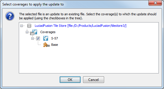
A dialog lets you select the coverages to which you want to apply the update. Select the check boxes of the coverages that require the update, and click OK.
Once the update has been added, you still need to commit the update, and fuse it.
Handling fusion failures
Sometimes, failures are encountered during a data fusion. The Fusion Engine distinguishes between non-fatal failures and fatal failures.
- Non-fatal failures
-
occur because of broken source data, or because of an unsupported feature in the source data. Data that causes non-fatal failures is gracefully skipped and reported when the fusion job finishes. Fusion will finish, but the skipped data will be missing from the resulting coverage.
- Fatal failures
-
occur when an unexpected error occurs, or when there are too many non-fatal failures. They prevent a fusion job from finishing. If the number of non-fatal failures reaches a certain threshold, the non-fatal failures become fatal, and the fusion job will fail. The default threshold is 1000 for raster data. See Overriding default failure thresholds for more information about changing these thresholds.
Inspecting non-fatal failures
To see a list of non-fatal fusion failures, click the exclamation mark button in the toolbar of the job manager panel.
If the exclamation mark button is grayed out, there were no non-fatal failures or the fusion job has not finished yet.
Overriding default failure thresholds
You can override default failure thresholds for raster data. To do so, change the number specified in the system property
com.luciad.fusion.engine.rasterFailureThreshold=<whole number>.
|
If you want to override the default failure thresholds when you are running a fusion on the server, set the system properties on the server system. |
Replicating Tile Store data
The Data Connectivity Manager allows you to manage data that is common to multiple Tile Stores through replication: you can copy data from a master Tile Store to one or more slave Tile Stores.
A Tile Store replication setup consists of:
-
A master Tile Store, containing the data to be replicated
-
One or more slave Tile Stores, containing the replicated data, often confined to a specific area of interest.
-
Tile Store resources that need to be partially or completely replicated from the master to the slave. These resources may be assets, coverages, or themes. The resources consist of data and metadata. Slaves may have additional local coverages beside those replicated from the master
During the replication process, a Fusion Engine first copies the metadata from the master to the slave, and then the data, until the contents of the master and the slave are consistent with each other.
This section describes how to configure Tile Store replication using the DCM. For more information about how replication works, see the `Replicating Tile Store data' section in the Tiling Engine developer’s guide.
Setting up Tile Store replication in the DCM
To configure Tile Store replication in the DCM:
-
Connect the DCM to the target slave Tile Store.
-
Disconnect the DCM from any other Tile Stores. If you are connected to multiple Tile Stores, you cannot replicate Tile Store data, so make sure you are connected to the slave only.
-
Right-click on the Tile Store in the Tile Store Manager tab, and select Replicate data from master Tile Store from the context menu. The Select master Tile Store to replicate data from dialog opens.
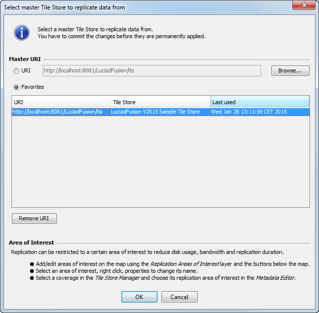 Figure 24. Selecting the master Tile Store for data replication
 -
Select a source Tile Store as the master by specifying its URI, or selecting it from the Favorites list, and click OK. You have now entered replication mode:
-
A layer Replication Areas of Interest is added to the map.
-
The Tile Store Manager panel shows the differences between the slave and master: Master coverages and assets are displayed in green. Slave coverages that will be deleted during replication have been struck-through.
-
The Commit and Revert buttons become available.
If you choose to restrict replication to a specific area of interest to reduce disk usage, bandwidth, or duration, proceed to the next step. If you want to replicate all master Tile Store data, skip the next step.
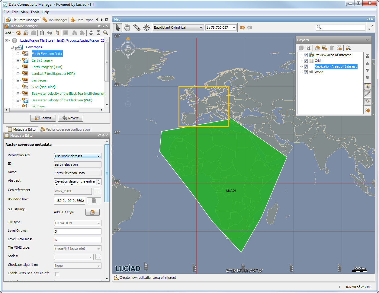 Figure 25. Defining an Area of Interest on a coverage
 -
-
To specify an area of interest, use the drawing tool buttons below the map:
-
In the Replication Areas of Interest map layer, select Create new replication area of interest in the drawing tool bar below the map.
-
Draw an area of interest on the map.
-
To assign a name to the Area of Interest, double-click it, and change its name in the Object Properties panel.
-
Select one or more coverages in the Tile Store Manager panel, and choose the Area of Interest in the Replication AOI field of each coverage’s Metadata Editor.
You can only limit the replication to the AOI of a coverage if you select the AOI in the metadata editor. If you do not select it, the whole coverage will be replicated.
During replication, only those master tiles or master asset sources that overlap with the AOI are filtered and stored on the slave.
To find out how to handle existing coverages on the slave and master Tile Stores, see Preserving and excluding coverages from replication.
-
-
Click Commit, and click OK in the Commit Tile Store dialog. The master Tile Store metadata is committed to the slave Tile Store.
-
Create and start the jobs by clicking Start jobs. All the data selected from the master Tile Store is replicated to the slave Tile Store. You leave replication mode, and the Replication Areas of Interest layer is no longer visible.
|
While replication is ongoing, the view consistently displays the old data. Once replication finishes, it will switch to the new data. |
Aborting the replication
To leave replication mode at any time, click the Revert button at the bottom of the Tile Store Manager panel.
Preserving and excluding coverages from replication
By default, any coverage that is present on the slave tile story only, will be deleted during replication. In the Tile Store Manager panel, the coverage name will be struck-through. If you want to preserve the slave coverage, right-click the coverage while in replication mode, and select the Revert option.
You can also use this option to prevent that the slave coverage is updated with data from the master coverage, or to exclude a coverage on the master Tile Store from replication to the slave.
Ensuring data consistency
You must configure data consistency on the slave, and set its "commit policy" to PER_COVERAGE. You cannot do this through the DCM. You need to configure this in the deployment descriptor web.xml.
A PER_COVERAGE commit policy ensures that the view on the coverage data is consistent during the replication process. As long as replication
for that coverage is ongoing, you will be viewing the old data consistently.
When replication finishes for that coverage, the view consistently switches to the new data.
Specific use cases of the Data Connectivity Manager
This section describes a few use cases of the Data Connectivity Manager that fall outside the typical use case as described in A typical use case of the Data Connectivity Manager.
Creating a new Tile Store
Creating a new Tile Store using the Data Connectivity Manager consists of the following steps:
-
Go to the Tile Store Manager tab and click on the
icon. Select Tile Store from the drop-down list.
-
In the Tile Store URI dialog box, select the URI radio button and browse for an existing directory or create a new directory for the Tile Store. You can choose any local or remote location on your file system or enter an
httpaddress. -
Click on Open to add this location. If you cannot connect to a remote Tile Store, you can create a new local Tile Store and export the data to a remote Tile Store later, as described in Exporting coverages to a Tile Store.
-
Click on the OK button to add the Tile Store to the chosen location.
The Tile Store Manager tab adds a new Tile Store to the list including empty folders for coverages, assets, and themes. To add data to the Tile Store you need to:
-
Load new data (assets) as described in Loading new data.
-
Add data to coverages in the Tile Store as described in Adding data to a Tile Store.
-
Optionally, add coverages to a theme as described in Adding a coverage to a theme.
-
Commit the changes to the Tile Store as described in Committing changes to the Tile Store.
-
Run the required fusion jobs as described in Running a fusion job.
Accessing a Tile Store with multiple Data Connectivity Manager sessions
The general use case of the Data Connectivity Manager is to manage one Tile Store by one person at a time. Nevertheless, it is possible to have multiple sessions of the Data Connectivity Manager running which can access the same Tile Store at the same time. In this case, any changes committed to the Tile Store from one session first have to be ready before changes from another session can be made to the same Tile Store. When it is not possible to commit changes to a Tile Store because of concurrent commits, an error message will appear.
Appendix A: Supported formats
Table 1, “Default supported file formats” shows the data formats and corresponding file extensions that the Data Connectivity Manager supports by default. Note that it is required for a file to have georeference information associated with it. This information can be available in the file itself or in an additional file, depending on the file format.
|
File type |
File name/extension |
Description |
|
ACE2. |
.ace2 |
Raster format decoded using GDAL |
|
ArcInfo Binary Grid |
.adf |
Raster format decoded using GDAL |
|
ArcInfo Export E00 Grid |
.e00 |
Raster format decoded using GDAL |
|
AIXM. See Notes on AIXM support. |
.xml |
Aeronautical Information Exchange Model |
|
Azavea Raster Grid |
.arg, .json |
Raster format decoded using GDAL |
|
BCI |
.matrixmap |
Document de Maitrise des Interfaces (ICD) |
|
BIL |
.bil |
Band Interleaved by Line |
|
BSB Nautical Chart |
.kap |
Raster format decoded using GDAL |
|
CADRG |
.toc |
Compressed ARC Digitized Raster Graphic |
|
CGM |
.cg, .cgm.gz, .cgm.zip |
Computer Graphics Metafile |
|
Convair PolGASP. |
.img |
Raster format decoded using GDAL |
|
DEM |
.dem, .dem.gz, .dem.zip |
Digital Elevation Model |
|
DIMAP |
.dim |
Digital Image Map |
|
DMED |
.dmed |
Digital Mean Elevation Data |
|
DTED |
.dt0, dt1, dt2 |
Digital Terrain Elevation Data |
|
ECDIS S-57/S-63 |
.000, .031 |
Electronic Chart Display and Information System (products ENC, IENC and AML) |
|
ECRG |
toc.xml |
Enhanced Compressed Raster Graphic |
|
ECW |
.ecw |
Enhanced Compressed Wavelet |
|
ELAS DIPEx |
Raster format decoded using GDAL |
|
|
ENVI .hdr Labelled Raster |
.hdr |
Raster format decoded using GDAL |
|
EOSAT Fast Format |
Raster format decoded using GDAL |
|
|
ERDAS Imagine |
.img |
Raster format decoded using GDAL |
|
ERDAS Imagine Raw |
.raw |
Raster format decoded using GDAL |
|
ETOPO |
.ETOPO2.raw.bin, .ETOPO2v2_MSB.raw, .ETOPO5.DAT |
Electronic Topography/bathymetry |
|
GDAL Virtual |
.vrt |
Raster format decoded using GDAL |
|
GeoSpot |
.dsc, .rep |
Geospatial PDF |
|
|
Portable Document Format |
GeoTIFF. See Notes on GeoTIFF support. |
|
.tif, .tiff |
Geo Tagged Image File Format |
GML Simple Features |
|
.gml32, .gml31, .gml3, .gml, .xml |
Geography Markup Language |
Golden Software ASCII Grid |
|
Raster format decoded using GDAL |
Golden Software Binary Grid |
|
|
Raster format decoded using GDAL |
Golden Software Surfer 7 Binary Grid |
|
|
Raster format decoded using GDAL |
GRASS ASCII Grid |
|
|
Raster format decoded using GDAL |
GRIB V1/V2 |
|
|
.grb, .grib2., .grb2, .dat |
GRIdded Binary |
GXF Grid eXchange File |
|
.gxf |
Raster format decoded using GDAL |
HDF5 |
|
.hdf, .h5, .he5, .hdf5 |
HF2/HFZ heightfield raster |
.hf2 |
|
Raster format decoded using GDAL |
JAI |
.jai |
|
Java Advanced Imaging |
JPEG 2000 |
.jp2, .j2k |
|
Joint Photographic Experts Group |
WMTS |
WMTS server URLs |
|
WMTS Protocols |
LuciadFusion Tile Store. See Notes on LuciadFusion Tile Store support. |
|
|
Magellan BLX Topo |
.blx, xlb |
Raster format decoded using GDAL |
|
Microstation DGN V7/V8. See Notes on DGN support. |
.dgn |
DesiGN |
|
MAP/MIF |
.mif, .map, .mif.gz, .map.gz, .mif.zip, .map.zip |
MapInfo/MapInfo Interchange Format |
|
MrSID |
.sid |
Multiresolution Seamless Image Database |
|
NASA ELAS |
Raster format decoded using GDAL |
|
|
NITF. See Notes on NITF support. |
.ntf |
National Imagery Transmission Format |
|
NetCDF |
.nc, .netcdf, .xml(NcML file) |
NOAA .gtx vertical datum shift |
|
.gtx |
Raster format decoded using GDAL |
Oracle Spatial. See Notes on Oracle Locator / Spatial support. |
|
.ogr (GeoRaster data) |
Raster |
.rst |
|
Shape |
.shp, .shp.gz, .shp.zip |
SwissTopo DHM25 |
|
.mlt, .mbl |
SwissTopo Digital Height Model |
TAB |
|
.tab |
MapInfo TAB |
TFW |
|
.tfw |
Tiff World |
USRP/ASRP/ADRG |
|
*01.thf, *01.gen, *01.qal, .sou, and .img |
UPS/UTM Standard Raster Product, ARC Standard Raster Product, ARC Digitized Raster Graphic |
USGS LULC Composite Theme Grid. |
|
Raster format decoded using GDAL |
USGS First Generation DOQ . |
|
|
.doq |
Raster format decoded using GDAL |
USGS New Labelled DOQ . |
|
.doq |
Raster format decoded using GDAL |
SGI Image Format |
|
.bw, .rgb, .rgba, .sgi |
Raster format decoded using GDAL |
Snow Data Assimilation System |
|
.hdr |
Raster format decoded using GDAL |
SRTM HGT format |
|
.hgt, .DEM |
Raster format decoded using GDAL |
VTP Binary Terrain Format. |
|
.bt |
Raster format decoded using GDAL |
PostgreSQL PostGIS See Notes on PostgreSQL PostGIS support |
Notes on AIXM support
-
The supported versions of AIXM are 3.3, 4.0, 4.5 and 5.1.
-
The AIXM data can only be fused into coverages of type IMAGE. The fusion process rasterizes the AIXM data into images.
-
Labels are not supported. They are silently ignored.
-
Filtering on feature type within a file is not supported. All feature types within a file are included.
Notes on DGN support
-
The supported versions of DGN are V7 and V8.
-
The DGN data can only be fused into coverages of type IMAGE. The fusion process rasterizes the DGN data into images.
-
Support for DGN in LuciadFusion depends on the Open Design Alliance DGN library. Limitations of this library also apply on DGN support in LuciadFusion. More information about this library can be found on http://www.opendesign.com/the_oda_platform/tg.
Notes on GeoTIFF support
-
The BigTIFF variant (enabling GeoTIFF file sizes larger than 4 GB) is also supported.
Notes on Oracle Locator / Spatial support
-
The supported versions of the Oracle Spatial / Locator databases are V8 and higher.
-
The connection with the Oracle database needs to be defined in a properties file. To access GeoRaster data, this is a file with .ogr extension; for more information about its contents, please refer to the guide Oracle_Spatial_DeveloperGuide.pdf
Notes on PostgreSQL PostGIS support
-
The connection with the PostGIS database needs to be defined in a properties file with a .pgs extension. For more information about its contents, refer to the Decoder properties section in the guide PostgreSQL_DeveloperGuide.pdf.
Notes on LuciadFusion Tile Store support
-
A specific coverage of a LuciadFusion Tile Store can be used as asset source.
-
Support is limited to LuciadFusion raster coverages.
-
A LuciadFusion coverage is identified by a URL of the form
http://my.server:8081/LuciadFusion/lts?COVERAGE_ID=mycoverageid. For files you can use the formfile:/tmp/MyTileStoreDir?COVERAGE_ID=mycoverageid.