A vertical view is used to visualize the third dimension of a list of points. Figure 1, “An example of a vertical view” shows the vertical view of a flight, for instance.
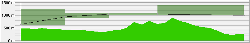
A vertical view typically shows a main profile and its associated sub-profiles. The flight profile in Figure 1, “An example of a vertical view” is the main profile. As sub-profiles, Figure 1, “An example of a vertical view” shows the altitude range between which an aircraft has to fly and the terrain profile. The line section drawn between two successive points of the main profile is called a segment.
A sub-profile can contain different points per main profile segment. For each of these sub-profile points, it is possible to retrieve the minimum and maximum altitude. A sub-profile is divided into sub-profile steps for each segment of the main profile. The number of steps of the sub-profile is equal to the number of sub-profile points in a segment minus one. In Figure 1, “An example of a vertical view”, the altitude range sub-profile has one step for each segment. The terrain sub-profile step has multiple steps for each segment. A sub-profile step has a ratio, that is the percentage on the X-axis it represents, relative to the segment of the main profile.
Modeling the profile
To model the profile of a vertical view, LuciadLightspeed provides the interface ILcdVVModel . An ILcdVVModel holds the main profile points of the vertical view and the information about every sub-profile associated with the main profile.
You can add a javax.swing.event.ChangeListener to an ILcdVVModel to receive a notification when the internal state of the model has changed and recalculation is required. For more information
on listening to changes, refer to Notifying objects of changes with listeners.
Implementations of ILcdVVModel provide methods to:
-
Get the number of points of the main profile and get the point at a specified index
-
Get the distance between two points on the main profile
-
Indicate if editing of the main profile is allowed and change the Z dimension of a point on the main-profile by dragging it
-
Get the number of sub-profiles
-
Get the number of points of a sub-profile in a specified segment of the main profile
-
Get the minimum or the maximum altitude for a specific sub-profile-point
-
Get the step length ratio of a given sub-profile step
-
Manage and notify change listeners
ILcdVVModel implementations
LuciadLightspeed offers an ILcdVVModel implementation, TLcdVVTerrainModel, that shows the profile of the polyline as the main profile, and the terrain profile as a sub-profile. The lightspeed.vertical sample shows how to use this ILcdVVModel.
Adding the profile to the view
To add a profile to the view, LuciadLightspeed provides the interface TLcdVVJPanel. A TLcdVVJPanel is a javax.swing.JPanel that allows to display one main profile and a number of sub-profiles that are associated with the main profile.
Associated with a TLcdVVJPanel are:
-
An
ILcdVVModel: the model that contains the main profile points and the information about the associated sub-profiles, described in Modeling the profile -
An
ILcdVVRenderer: a renderer for the vertical view that is responsible for the way the vertical view is drawn, described in Rendering the profile -
An
ILcdVVGridRenderer: a grid renderer to which the painting of the grid is delegated, described in Painting the grid -
An
ILcdVVGridLineOrdinateProvider: a grid-line ordinate provider that determines the range of the vertical view after snapping and the visible grid-line and sub grid-line ordinates, described in Using an ILcdVVGridLineOrdinateProvider -
An
ILcdVVXAxisRenderer: a renderer for the X-axis that is responsible for decorating the X-axis, described in Decorating the X-axis
Configuring a TLcdVVJPanel
The TLcdVVJPanel provides some methods to set the ILcdVVModel and the renderers. If the ILcdVVModel is set, the TLcdVVJPanel is automatically registered as
javax.swing.event.ChangeListener to display changes immediately. Methods are also provided to indicate if the X-axis should be labeled, if the main points
should be labeled, and if the vertical cursor should be visible. The different renderers describe the way in which the labels
and vertical cursor are painted if they are visible.
Additionally, some methods are provided to change the part of the model that has to be visible in the vertical view:
-
indicate a start point and an end point of the main profile to take into account
-
define a ratio (between 0 and 1) of the main profile to hide at the left and the right side
-
set the lowest and the highest altitude that should be painted when displaying values
Creating a TLcdVVJPanel with controllers
A TLcdVVWithControllersJPanel contains a TLcdVVJPanel and some controllers that allow users to change the values that define the visible part of the model in the vertical view.
You can define in the constructor of the TLcdVVWithControllersJPanel which controllers to include.
Listening to cursor changes
The user can position a vertical cursor anywhere along the main profile. When the position of the
cursor changes, all the registered ILcdVVCursorChangeEventListener objects are notified. The TLcdVVCursorChangeEvent contains the point of the main profile on the left of the cursor position, on the right of the cursor position, and the percentage
of the segment on the left side of the cursor.
Rendering the profile
An ILcdVVRenderer is responsible for rendering, or painting, the main profile and the sub-profiles. You can render a profile in (a combination
of) the following modes:
-
ILcdVVRenderer.NO_PAINTING: the profile is not painted -
ILcdVVRenderer.TOP_LINE: draws a line that is constituted by invoking maxZ of the points of a sub-profile -
ILcdVVRenderer.BOTTOM_LINE: draws a line that is constituted by invoking minZ of the points of a sub-profile -
ILcdVVRenderer.LEFT_LINE: draws a line that connects the leftmost point of the topline and the leftmost point of the bottomline -
ILcdVVRenderer.RIGHT_LINE: draws a line that connects the rightmost point of the topline and the rightmost point of the bottomline -
ILcdVVRenderer.FILLED: draws a topline and bottomline and fills the space between them -
ILcdVVRenderer.POLYGON: draws a topline, bottomline, leftline and rightline
For the main profile, only NO_PAINTING and TOP_LINE are valid options.
An ILcdVVRenderer provides some basic methods to paint the different parts of the main profile and the sub-profiles. The basic methods for
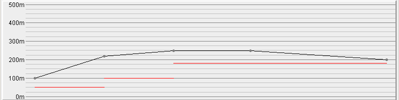
painting the main profile are: paintPointIcon, drawProfileLine, paintPointLabel. The paintYAxisParallelLine method paints a vertical line from a given point on the main profile to the X-axis. The paintVerticalCursor method paints a vertical cursor. The basic methods for painting the sub-profiles are drawSubProfileLine and fillSubProfileStepPolygon. The sub-profile in Figure 1, “An example of a vertical view” is rendered in FILLED mode. Figure 2, “An example of rendering mode BOTTOM_LINE” shows the same example, but with the sub-profile rendered in BOTTOM_LINE mode.
The default implementation of ILcdVVRenderer is TLcdDefaultVVRenderer . Another implementation is TLcdDefaultVVRendererJ2D that you can only use with Java 2D.
Configuring a TLcdDefaultVVRenderer
TLcdDefaultVVRenderer has several properties, which you can change by means of the corresponding set methods. Program: Creation and configuration of an TLcdDefaultVVRenderer shows the creation of a TLcdDefaultVVRenderer and its configuration using several set methods:
-
setMainProfileRenderingModeto set the rendering mode for the main profile -
setProfileColorto set the color for the main profile -
setSubProfileRenderingModeto set the rendering mode for the sub-profiles -
setSubProfileColorto set the color for the sub-profiles
TLcdDefaultVVRenderer (from samples/gxy/vertical/MainPanel)
TLcdDefaultVVRendererJ2D viewRenderer = new TLcdDefaultVVRendererJ2D();
verticalView.setVVRenderer(viewRenderer);

// only label the highlighted point of the main profile
verticalView.setPaintAllLabels(false);
viewRenderer.setPointFormat(new VVAltitudePointFormat(verticalView));

// The main profile (our flight plan) is rendered using a line connecting the points.
viewRenderer.setMainProfileRenderingMode(ILcdVVRenderer.TOP_LINE);
// The subprofile (the terrain) is rendered as filled polygons
// are drawn at each subProfileStepIndex.
viewRenderer.setSubProfileRenderingMode(ILcdVVRenderer.FILLED | ILcdVVRenderer.TOP_LINE);

// Color configuration.
viewRenderer.setPointIcon(MapColors.createHandleIcon());
viewRenderer.setProfilePaint(Color.BLACK);
viewRenderer.setSubProfilePaintArray(aColors);
viewRenderer.setMainProfileLabelPaint(Color.DARK_GRAY);
Decorating the X-axis
An ILcdVVXAxisRenderer is responsible for decorating the X-axis. This interface only contains two methods: getHeight to get the number of pixels that the renderer needs for decorating the X-axis and paintOnXAxis to decorate the X-axis.
ALcdVVXAxisRendererJ2D is an abstract implementation of ILcdVVXAxisRenderer. It paints icons on the X-axis and paints labels underneath the icons. The labels can be rotated over a rotation angle.
This class can only be used with Java 2D.
Painting the grid
All the painting that needs to be done for the grid is delegated to an ILcdVVGridRenderer . This interface provides methods for painting the basic grid lines, for painting sub grid lines, for rendering ordinate
labels for the grid, and for retrieving the font size of the labels.
TLcdDefaultVVGridRenderer is a default implementation of ILcdVVGridRenderer. This class provides some set methods to customize the default behavior.
Using an ILcdVVGridLineOrdinateProvider
An ILcdVVGridLineOrdinateProvider is responsible for the snapped range and the grid-line ordinates of the vertical view. The interface provides methods for
retrieving the range after snapping and for retrieving the grid-line and sub grid-line ordinates.
TLcdDefaultVVGridLineOrdinateProvider
is a default implementation of ILcdVVGridLineOrdinateProvider.
A use case of the vertical view
This section describes a use case that shows how to implement a vertical view that displays the altitude of some flights. Each flight is a list of 3D points. A normal view only shows the first two coordinates(X,Y) of each of the points. The vertical view is used to show the vertical profile of the flight. In this case, one sub-profile is associated with the view that expresses the altitude-range between which the aircraft has to fly. For each segment of the flight, the minimum and maximum altitudes are shown. Thus, for each segment of the main profile, the sub-profile has only one step. Because there is just one sub-profile step for each segment, the ratio of each of the sub-profile steps is 1.
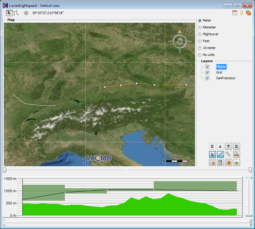
Figure 3, “The vertical view of the use case” shows three panels: the upper panel contains a 2D view with two flights. If the user selects one of the flights, the vertical view of the selected flight is shown in the bottom panel. The panel on the right enables a user to change the altitude unit on the vertical view.
A TLcdVVWithControllersJPanel is used to display the vertical view. This javax.swing.JPanel contains a TLcdVVJPanel. To configure a TLcdVVJPanel, you can set an ILcdVVModel, an
ILcdVVRenderer, an ILcdVVGridRenderer and an ILcdVVXAxisRenderer.
FlightVVModel is an ILcdVVModel that contains all the information about flights and the
altitude-ranges. TLcdDefaultVVRenderer is used as ILcdVVRenderer and some of its properties are configured using its set methods. Since no ILcdVVGridRenderer is set in the sample, the default implementation TLcdDefaultVVGridRenderer is used. This implementation can take the altitude unit of the vertical view into account to display labels.
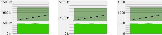
Notice that changing the unit might have an influence on the upper and lower limits of the vertical view as
it attempts to set round numbers as the limits (see Figure 4, “Setting units on the vertical view (meter, feet, none)”). The X-axis is not decorated, so no ILcdVVXAxisRenderer is set.
Creating the flight model
FlightVVModel is an implementation of ILcdVVModel. It holds the main profile points of a flight and the minimum and maximum altitudes associated to the segments of the flight.
ILcdVVModel used for flights (from samples/gxy/vertical/FlightVVModel)
public class FlightVVModel extends ALcdVVModel {

  private final Flight fFlight;
  private final ILcdModel fModel;

  public FlightVVModel(Flight aFlight, ILcdModel aModel) {
    fFlight = aFlight;
    fModel = aModel;
    // informs the vertical view of any changes in the model
    fModel.addModelListener(aEvent -> fireChangeModel());
  }

  // points of the main profile
  @Override
  public ILcdPoint getPoint(int aIndex) throws IndexOutOfBoundsException {
    return fFlight.getPoint(aIndex);
  }

  // there is only one sub-profile: the air route associated to each segment
  @Override
  public int getSubProfileCount() {
    return 1;
  }

  // for each segment, the sub-profile has just 2 points: the begin point and
  // the end point of the segment
  @Override
  public int subProfilePointCount(int aSegmentIndex, int aSubProfileIndex)
      throws IndexOutOfBoundsException {
    return 2;
  }

  // the sub-profile contains one step for each segment so the ratio of the
  // step length is always 1
  @Override
  public float stepLenghtRatio(int aSubProfilePointIndex, int aSegmentIndex, int aSubProfileIndex)
      throws IndexOutOfBoundsException {
    return 1;
  }

  @Override
  public double minZ(int aSubProfilePointIndex, int aSegmentIndex, int aSubProfileIndex)
      throws IndexOutOfBoundsException {
    return fFlight.getRouteMinAltitude(aSegmentIndex);
  }

  @Override
  public double maxZ(int aSubProfilePointIndex, int aSegmentIndex, int aSubProfileIndex)
      throws IndexOutOfBoundsException {
    return fFlight.getRouteMaxAltitude(aSegmentIndex);
  }
// ...
Program: An implementation of ILcdVVModel used for flights shows a part of the implementation of FlightVVModel. The implementation of the methods of ILcdVVModel is straightforward.
Program: Construction and configuration of the TLcdVVWithControllersJPanel shows the creation and configuration of the
TLcdVVWithControllersJPanel, the javax.swing.JPanel that contains the vertical view.
TLcdVVWithControllersJPanel (from samples/gxy/vertical/MainPanel)
TLcdVVJPanel verticalView = new TLcdVVJPanel();

// enable X-axis labels
verticalView.setXAxisLabeled(true);
verticalView.setVVXAxisRenderer(new VVXAxisDistanceRenderer());

// enable Y-axis grid lines in flight levels or meters/feet
verticalView.setVVGridLineOrdinateProvider(new VVGridLineOrdinateProvider());
TLcdDefaultVVRendererJ2D viewRenderer = new TLcdDefaultVVRendererJ2D();
verticalView.setVVRenderer(viewRenderer);

// only label the highlighted point of the main profile
verticalView.setPaintAllLabels(false);
viewRenderer.setPointFormat(new VVAltitudePointFormat(verticalView));

// The main profile (our flight plan) is rendered using a line connecting the points.
viewRenderer.setMainProfileRenderingMode(ILcdVVRenderer.TOP_LINE);
// The subprofile (the terrain) is rendered as filled polygons
// are drawn at each subProfileStepIndex.
viewRenderer.setSubProfileRenderingMode(ILcdVVRenderer.FILLED | ILcdVVRenderer.TOP_LINE);

// Color configuration.
viewRenderer.setPointIcon(MapColors.createHandleIcon());
viewRenderer.setProfilePaint(Color.BLACK);
viewRenderer.setSubProfilePaintArray(aColors);
viewRenderer.setMainProfileLabelPaint(Color.DARK_GRAY);
// Constructs a TLcdVVWithControllersJPanel that adds controllers to zoom in on the X and Y axis.
TLcdVVWithControllersJPanel vvWithControllers =
    new TLcdVVWithControllersJPanel(aVerticalView,
                                    LEFT_RIGHT_OFFSET | TOP_BOTTOM_OFFSET);