The Terrain Analysis Engine provides functionality to compute the visibility from a shape to another shape. This computation
is illustrated in the sample samples.tea.gxy.visibility.MainPanel. By using the shape-to-shape visibility computations, as discussed, the following questions can be answered: Is a point visible
from an area? Are parts of the area visible from a point? Is a part of a polyline visible from an area? Are parts of an area
visible from a polyline?
Shape-to-shape visibility
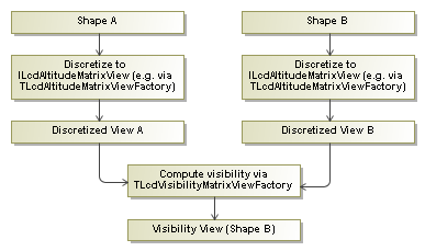
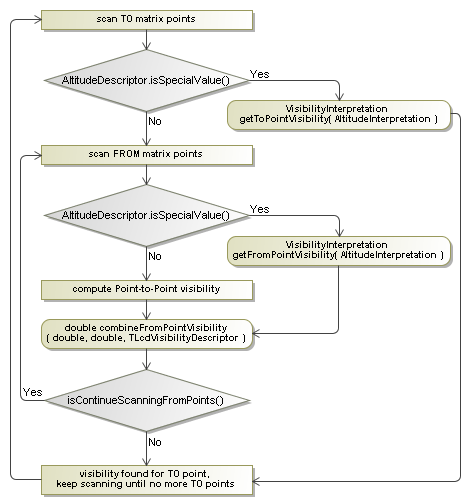
Figure 1, “Flow chart on how to compute a shape-to-shape visibility.” shows the steps of the algorithm to compute a shape-to-shape visibility. In the first step, the shapes need to be discretized
into ILcdAltitudeMatrixView objects. These objects are then passed to the TLcdVisibilityMatrixViewFactory which produces an ILcdVisibilityMatrixView that provides information on the visibility of the second shape.
A visibility computation between two discretized shapes is split into a number of point-to-point computations. A single point-to-point computation requires two points, some altitude information and a propagation function, as explained in LOS calculation from point to point. To be consistent with the point-to-point computation, the input shapes are discretized into a data structure which adds altitude information for each discretized point.
Discretizing a shape
The class TLcdAltitudeMatrixViewFactory can create the discretized views for an ILcdPoint, an ILcdPolyline and an ILcdShape.
-
a 1x1
ILcdAltitudeMatrixViewwhich represents a single point, see Figure 2, “AnILcdAltitudeMatrixViewexample for a point.”.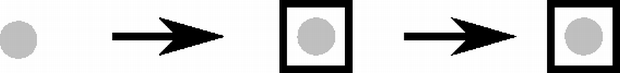 Figure 2. An
ILcdAltitudeMatrixViewexample for a point. -
a 1xN
ILcdAltitudeMatrixViewwhich represents an array of points, see Figure 3, “AnILcdAltitudeMatrixViewexample for a polyline.”. Both the segment points (gray) and the intermediate points (green) are added to the matrix view.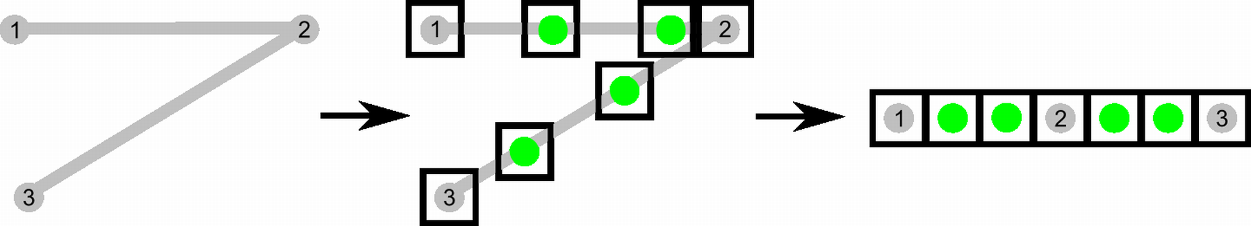 Figure 3. An
ILcdAltitudeMatrixViewexample for a polyline. -
a MxN
ILcdAltitudeMatrixViewwhich represents a matrix of points, see Figure 4, “AnILcdAltitudeMatrixViewexample for a shape.”. Both the green and red dots are added to the matrix view. The red dots represent points outside the shape. These points have to be marked so that they are not taken into account for the computations later on.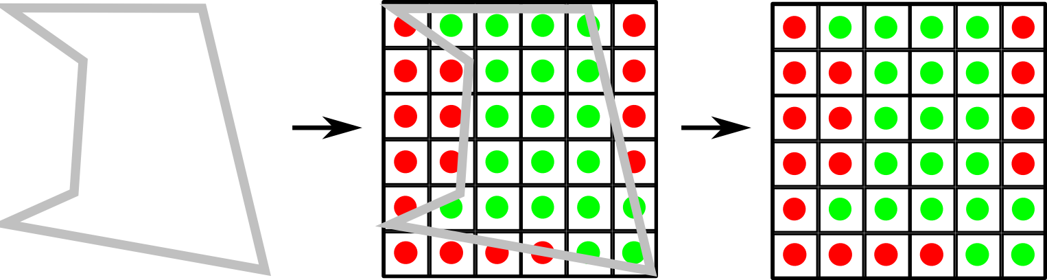 Figure 4. An
ILcdAltitudeMatrixViewexample for a shape.
Note that, because a line shape (for example an ILcdPolyline) does not have an area, there will not be enough discretization points to represent the line shape. Almost all points will
lie outside the shape which makes the result in general useless. This discretized view is therefore only usable for area shapes
like ILcdArcBand instances, ILcdPolygon instances, …
Next to the discretized shapes, the factory methods require an altitude provider and some discretization parameters (step, line type,…). The altitude provider should provide an altitude value for each point in the discretized view. The following images illustrate two altitude providers available in the package. The green lines represent the returned altitude for the points between A and B. The discretization parameters are used to discretize the specified shape. The discretization step represents the distance, defined in meters, between the discretization points. The discretization line type determines how to interpolate the polyline shape.
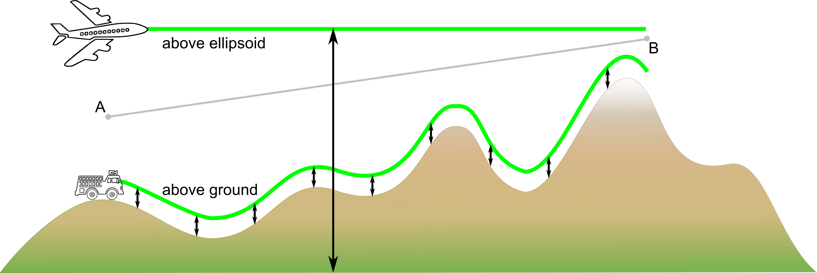
TLcdFixedHeightAltitudeProvider.
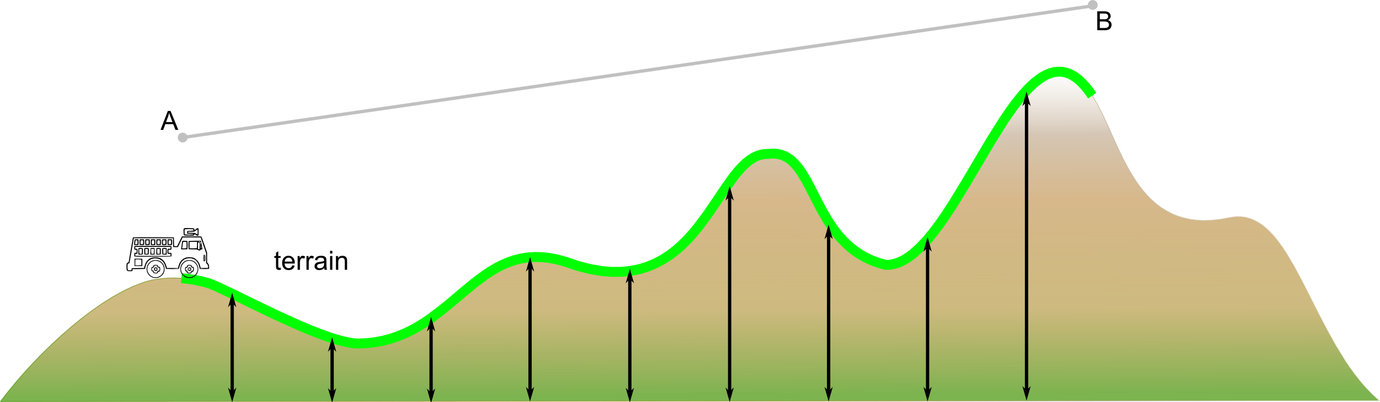
ALcdTerrainElevationProvider.
Note that special altitude values are required to represent points which lie outside the shape or outside the bounds of the
elevation data, and to represent points for which an invalid elevation value is found. These values are described in the TLcdAltitudeDescriptor. The descriptor converts double altitude values into TLcdAltitudeInterpretation instances and vice versa. The default altitude interpretations are:
-
TLcdAltitudeInterpretation.UNKNOWN_ELEVATION: the elevation value is invalid. -
TLcdAltitudeInterpretation.OUTSIDE_RASTER_BOUNDS: the point lies outside the bounds of the elevation data. -
TLcdAltitudeInterpretation.OUTSIDE_SHAPE: the point lies outside the shape that is being discretized.
Computing the visibility between two discretized shapes
When both shapes are discretized, the class TLcdVisibilityMatrixViewFactory can be used to compute the visibility between the two discretized shapes. The visibility factory will create a discretized
shape with the same points as the second discretized shape and will fill it with a visibility result for each discretized
point. To compute the visibility the following information is required:
-
Two discretized shapes: the first represents the shape from which one is looking, the second represents the shape at which one is looking.
-
A
ILcdP2PPropagationFunctionand a step size to compute the internal point-to-point visibilities. More information about the propagation function can be found in LOS calculation from point to point. -
A
TLcdVisibilityDescriptor: this descibes special visibility values in the resulting visibility matrix view. The descriptor converts double visiblity values intoTLcdVisibilityInterpretationinstances and vice versa. The most common visibility interpretations are:-
TLcdVisibilityInterpretation.VISIBLE: the point is visible. -
TLcdVisibilityInterpretation.INVISIBLE: the point is not visible. -
TLcdVisibilityInterpretation.UNCERTAIN: due to unknown or invalid values, the visibility cannot be computed and is uncertain.
-
The following flow chart describes how the visibility is computed and how the protected factory methods are used. All To points are processed as they are part of the visibility result. This means that, for each To point, a visibility value is required. For regular values, the From points are processed and the combined visibility value is used. For special values, the method getToPointVisibility provides the required visibility value. When processing the From points, a visibility value is required for all From points. For regular points, the result of the point-to-point intervisibility computation between the From point and the To point is used. For special points, the method getFromPointVisibility provides the visibility value. The From point visibility values are combined in the method combineFromPointVisibility. This results in the required visibility value for the To point that was being processed. The From point scanning can be stopped prematurely if the method isContinueScanningFromPoints determines that the current combined visibility value needs to be used and no other points need to be processed.
Shape-to-shape visibility example
The sample samples.tea.gxy.visibility.MainPanel demonstrates how the above explained visibility functionality can be used. The discretization of points, polylines and polygons
is handled as illustrated by Program: Discretization of points and polylines. and Program: Discretization of polygons..
samples/tea/AbstractVisibilityAction)
ILcdAltitudeMatrixView matrixViewPoint = ALTITUDE_MATRIX_VIEW_FACTORY.createPointAltitudeMatrixView(
    fPoint,
    fPointReference,
    2,                        // fixed height above ground
    TLcdCoverageAltitudeMode.ABOVE_GROUND_LEVEL,
    ALTITUDE_DESCRIPTOR,      // default descriptor
    fPointReference           // same as source reference
);

ILcdAltitudeMatrixView matrixViewPolyline = ALTITUDE_MATRIX_VIEW_FACTORY.createPathAltitudeMatrixView(
    aPolyline,
    aPolylineReference,
    ALTITUDE_PROVIDER,        // fixed height above ground
    stepSize,
    LINE_TYPE,                // geodetic line type
    ALTITUDE_DESCRIPTOR,      // default descriptor
    aPolylineReference        // same as source reference
);samples/tea/gxy/visibility/GXYVisibilityAction)
ILcdAltitudeMatrixView matrixViewShape = aAltitudeMatrixViewFactory.createAreaAltitudeMatrixView(
    aPolygon,
    aPolygonReference,
    aAltitudeProvider,        // fixed height above ground
    fDTEDRaster,
    fDTEDRasterReference,
    aAltitudeDescriptor,      // default descriptor
    aPolygonReference         // same as source reference
);
The TLcdVisibilityMatrixViewFactory is used to compute the visibility between two discretized shapes. Program: A point-to-polyline visibility computation. shows how the visibility is computed from a point to a polyline. In Program: A point-to-polygon visibility computation., the visibility is computed from a point to a polygon.
samples/tea/AbstractVisibilityAction)
ILcdMatrixView result = VISIBILITY_MATRIX_VIEW_FACTORY.createVisibilityMatrixView(
    matrixViewPoint,
    matrixViewPolyline,
    stepSize,
    fP2PPropagationFunction,
    VISIBILITY_DESCRIPTOR     // default descriptor
);samples/tea/AbstractVisibilityAction)
ILcdVisibilityMatrixView result = VISIBILITY_MATRIX_VIEW_FACTORY.createVisibilityMatrixView(
    matrixViewPoint,
    matrixViewShape,
    stepSize,
    fP2PPropagationFunction,
    VISIBILITY_DESCRIPTOR     // default descriptor
);
The result of the to-polyline visibility computation, which is a 1xN ILcdMatrixView, is shown using the sample painter VisibilityPainterPolyline. This painter draws a combination of green and red lines indicating visible and invisible parts of the polyline as illustrated
in the left part of Figure 8, “The result of the point-to-polyline and point-to-polygon visibility computation.”.
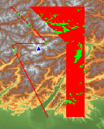
To be able to show the result of the to-polygon visibility computation, which is an MxN ILcdMatrixView, the matrix is converted into a raster containing green and red pixels indicating visible and invisible parts of the polygon.
The visibility raster is illustrated in the right part of Figure 8, “The result of the point-to-polyline and point-to-polygon visibility computation.”. For this conversion, the factory class TLcdMatrixViewRasterFactory is used as shown in the following code snippet.
samples/tea/AbstractVisibilityAction)
ILcdRaster raster = MATRIX_VIEW_RASTER_FACTORY.createEquivalentRaster(
    result,
    (ILcdGeoReference) fToPolygonLayer.getModel().getModelReference(),
    MATRIX_RASTER_VALUE_MAPPER
);