Providing elevation data
As its name states the ALcdTerrainElevationProvider provides elevation information based on terrain data. This is an abstraction, trying to hide where the elevation data comes
from. It is part of the strategy design pattern. It hides the specifics of the data formats and provides only that information
that you require for the next steps, in this case the altitudes.
Any kind of raster data could be considered terrain data by interpreting the pixel values in the image as heights. However, common data formats that are considered elevation data are Digital Mean Elevation Data (DMED)/Digital Terrain Elevation Data (DTED), Digital Elevation Model (DEM), Swiss Digital Height Model (DHM)[1], and ETOPO[2]. Other formats, like GeoTIFF and Band Interleaved by Line (BIL), can sometimes be interpreted as terrain elevation data. Note that the abstract class does not restrict elevation data to raster data, but most implementations will.
ALcdTerrainElevationProvider provides a mechanism to retrieve height values for a given location. The main extension for this class TLcdGXYViewBasedTerrainElevationProvider which acts as an ILcdLayeredListener to the view to keep track of layers which contain elevation data. These layers are filtered out through a filter which by
default selects the common formats above.
For performance reasons, the abstract class contains a preferred reference. This is the reference with the best performance
when used as a parameter in the method retrieveElevationAt. In general, the preferred reference should be the reference of the available elevation data to minimize the number of point
transformations.
Retrieving altitudes in a view
Retrieving altitudes in a GXY view
A TLcdTerrainProfileController is an ILcdGXYController for visualizing elevation information contained in a raster that is rendered in an ILcdGXYView. It uses a TLcdGXYViewBasedTerrainElevationProvider to provide
-
the altitude at the mouse location
-
the terrain cross-section along a geodesic line.
For the latter cross-section, the TLcdTerrainProfileController has an ILcdProfileView. The profile view is a separate view on which a terrain cross-section is shown when certain mouse actions are performed while
the TLcdTerrainProfileController is active.
In the package samples.tea.gxy.distance, an example is provided that can be started by running samples.tea.gxy.distance.MainPanel. The example demonstrates the TLcdTerrainProfileController.
Altitude at mouse location
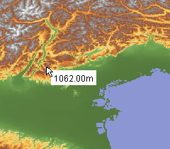
When moving the mouse over elevation data, the altitude at the mouse location is shown next to the cursor. This is illustrated in Figure 1, “Terrain elevation at mouse location.”. The actual rendering of the altitude is fully customizable.
Terrain cross-section along a geodesic line
When dragging the mouse, a geodesic line is drawn, connecting the start point and end point of the drag. This line is known
as the ghost line and its appearance can be changed via the properties ghostColor and ghostLineWidth. If an
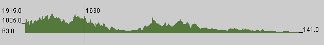
ILcdProfileView is associated with the TLcdTerrainProfileController, a cross-section of the terrain along this geodesic line will be shown on it. An example of such a cross-section view is
given in Figure 2, “Terrain cross-section with altitude at mouse location.”.
Program: Initializing a TLcdTerrainProfileController. shows how to associate an ILcdProfileView with the controller and how to set some visual properties.
samples/tea/gxy/distance/MainPanel)
TLcdTerrainProfileController terrainProfileController = new TLcdTerrainProfileController();
terrainProfileController.setProfileView(fProfileView);
terrainProfileController.setForeground(new Color(70, 100, 50));
terrainProfileController.setGhostColor(Color.black);
Viewing a terrain cross-section
An ILcdProfileView is a viewing component intended to show a cross-sectional terrain profile. In the Terrain Analysis Engine, there is one implementation,
TLcdProfileViewJPanel. This implementation is an extension of JPanel to show a cross-section of the terrain as shown in Figure 2, “Terrain cross-section with altitude at mouse location.”. This component has some additional functionality.
When left-clicking the mouse on the TLcdProfileViewJPanel, a vertical line is shown on top of the terrain cross-section and the altitude at that point is shown. This is illustrated
in Figure 2, “Terrain cross-section with altitude at mouse location.”.
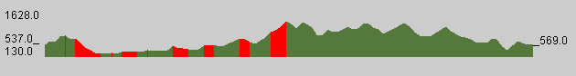
When right-clicking the mouse on the TLcdProfileViewJPanel, a simple line-of-sight analysis is performed with as center point the point where the last left-click was performed along
the ghost line. Visible sections are indicated in red, as is illustrated in Figure 3, “Line-of-sight along the cross-section.”.
Computing distance over terrain
Distance calculations in the Terrain Analysis Engine are always performed on an ellipsoid or a plane. While this is sufficient
when calculating distances in the air, this might not be a good approximation for distances over land. To this end the TLcdTerrainRulerController was created. This controller extends the TLcdAdvancedMapRulerController and uses a ALcdTerrainElevationProvider to gather elevation information on the points on the path between two points.
The package samples.tea.gxy.distance contains a sample which demonstrates the use of the TLcdTerrainRulerController. Program: Creating a new TLcdTerrainRulerController. shows how the ruler controller is created and how a terrain
elevation provider is assigned to it. The terrain elevation provider is setup with a model that contains elevation information.
In this sample the data is loaded from a DTED file which covers the area of the Alps in Northern Italy.
TLcdTerrainRulerController. (from samples/tea/gxy/distance/MainPanel)
fTerrainRulerController = new TLcdTerrainRulerController();
fTerrainRulerController.setTerrainElevationProvider(
    new TLcdGXYViewBasedTerrainElevationProvider(getView(), new TLcdFixedLevelBasedRasterElevationProvider()));
fTerrainRulerController.setSnappables(toolBar.getSnappables());
The TLcdAdvancedMapRulerController has multiple modes to define a path between two points. Two of those modes can be chosen
in the sample as shown in Program: Setting a mode on TLcdAdvancedMapRulerController.. The geodetic mode will follow the shortest path on the ellipsoid between the two points, while the rhumbline mode will follow
a path of constant azimuth. This path is discretisized and the elevation is sampled on the intermediate points. The terrain
distance is then computed using the theorem of Pythagoras. This ensures that distances taking terrain into account are greater
than distances not taking the terrain into account. Note however that due to effect of the terrain the geodetic path is no
longer garantueed to return the shortest distance between the two points as a highly elevated point may be on the geodetic
path while it is not in the rhumbline path. Keep in mind that unknown or invalid elevation values can be found during the
measurement. In this case, the terrain distance cannot be calculated and will remain "Unknown".
TLcdAdvancedMapRulerController. (from samples/tea/gxy/distance/MainPanel)
aRulerController.setMeasureMode(TLcdAdvancedMapRulerController.MEASURE_GEODETIC);
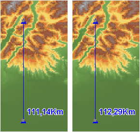
aRulerController.setMeasureMode(TLcdAdvancedMapRulerController.MEASURE_RHUMBLINE);The use terrain property, see Program: Taking terrain into account or not., enables you to switch taking the terrain into account. When set to false the ruler controller will revert to the behavior
of TLcdAdvancedMapRulerController for distance calculations. Figure 4, “Air distance and distance over terrain.” demonstrates the difference: on the left is the distance between the two points in the air, while the measurement on the
right takes into account the terrain beneath the path between the two points.
samples/tea/gxy/distance/MainPanel)
aRulerController.setUseTerrain(useTerrain);