This guide provides an introduction to the Dimensionally Extended Nine Intersection Matrix (DE-9IM) model on which
the ILcd2DAdvancedBinaryTopology interface is based.
An understanding of the key concepts of this model is required to create custom-defined topological relations.
You can find more information on the DE-9IM model in the OpenGIS Implementation Specification for Geographic information - Simple feature access.
Interior, boundary, and exterior
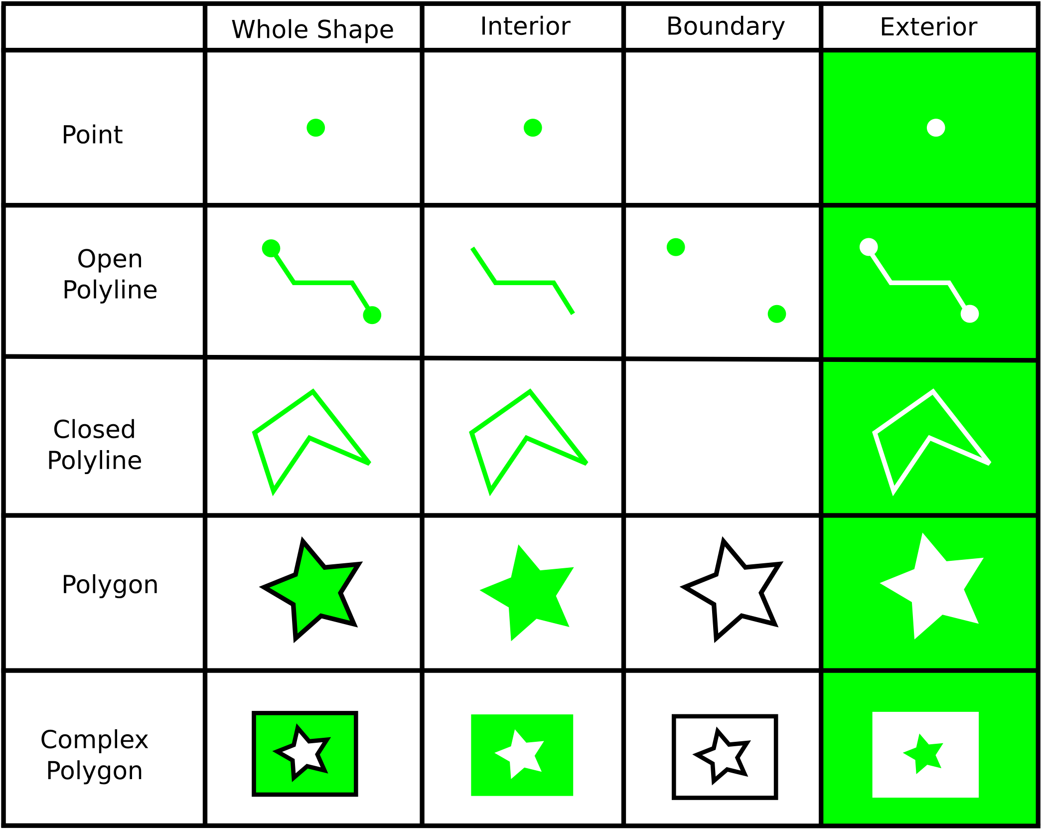
The DE-9IM model defines three disjoint sets for all shapes: the interior, the boundary, and the exterior. The interior and boundary sets are defined as follows for the following shapes:
-
Point
-
Interior: the point itself (0-dimensional).
-
Boundary: empty set, points are defined to have no boundary.
-
-
Open polyline
-
Interior: all points and segments, except the two endpoints (1-dimensional).
-
Boundary: the two endpoints (0-dimensional).
-
-
Closed polyline
-
Interior: all points and segments (1-dimensional).
-
Boundary: empty set.
-
-
Polygon
-
Interior: all points of the polygon, excluding the contour (2-dimensional).
-
Boundary: all points belonging to the contour of the polygon (1-dimensional).
-
-
Complex polygon
-
Interior: all points of the complex polygon, excluding the contours of the polygons (2-dimensional).
-
Boundary: all points belonging to at least one of the contours of the polygons (1-dimensional).
-
The following image provides a graphical illustration of these:
Intersection matrix
The (dimensionally extended nine) intersection matrix stores information about the way two shapes are topologically related. More specifically, the rows (columns) correspond with the interior, boundary, and exterior respectively of the first (second) shape. As a result, the DE-9IM is a 3x3 matrix containing nine elements.
This is illustrated in the table below where the first and second shape are denoted with S1 and S2, respectively.
|
|
|
|
|
|
|
* |
* |
* |
|
|
* |
* |
* |
|
|
* |
* |
* |
Each matrix element contains the dimension of the intersection of the two corresponding regions. This dimension has one of the following values:
-
F: no intersection (False) -
0: 0-dimensional intersection -
1: 1-dimensional intersection -
2: 2-dimensional intersection
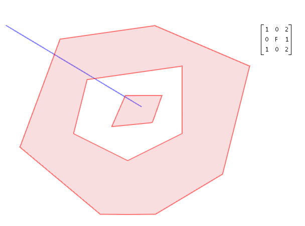
The image below shows an example of an intersection matrix of a complex polygon and a (poly)line. The complex polygon is the first shape, the line is the second shape.
Intersection matrix pattern
In the DE-9IM model, binary topological relations between two shapes are evaluated by:
-
computing the intersection matrix of these two shapes
-
checking whether this intersection matrix fulfills certain conditions
Each binary topological relation imposes its own set of conditions on the intersection matrix. In its simplest form, these conditions can be formulated as a single matrix pattern. A matrix pattern consists of a set of 9 pattern values, one for each element of the intersection matrix.
This pattern values can be one of the following:
-
T: the corresponding matrix element should be0,1or2 -
F: the corresponding matrix element should beF -
*: the corresponding matrix element can be anything -
0: the corresponding matrix element should be0 -
1: the corresponding matrix element should be1 -
2: the corresponding matrix element should be2
A single matrix pattern can be represented as a string of nine values in row major order (row by row).
For example, two shapes are disjoint if the interior and boundary of the first shape have no point in common
with either the interior or boundary of the second shape.
Therefore, the disjoint relation imposes that the first two elements of both the first and second row of the intersection
matrix should be F(alse).
This means that the disjoint relation corresponds with the single matrix pattern FF*FF****.
The question whether two shapes are disjoint can then be answered by computing their intersection matrix and checking whether
it matches this matrix pattern.
For instance, the complex polygon and polyline shown in Figure 2, “Example of an intersection matrix of a complex polygon and a (poly)line” have an intersection matrix 1020F1102 which does not match the pattern FF*FF**** so that we correctly find that both shapes are not disjoint.
Note that the interface ILcdIntersectionMatrixPattern in the Advanced GIS Engine component is not restricted to such a simple matrix pattern as mentioned above.
An ILcdIntersectionMatrixPattern represents any set of conditions imposed on an intersection matrix of two shapes.
In more complex cases, these conditions could be a logical combination of simple matrix patterns and/or depend on other parameters
such as the dimension of the involved shapes.
You can find an example of a more complex intersection matrix pattern in
Creating a custom topology relation.