When you are working with vector objects containing height information, you may want to visualize them as an extruded shape in a 3D view. A common example is building data with properties that define the vertical extent of the building.
Using the vector styling API, you can programmatically turn objects into extruded shapes during rendering and style them with a line and fill style. This
article shows you an alternative approach where you rely on OGC SLD/SE styling and use Luciad’s vendor-specific options in
a PolygonSymbolizer to enable extruded shapes:
-
extrudedShapeMinimum: takes either a property name or a constant value, indicating the minimum height in meters for the extruded shapes. -
extrudedShapeMaximum: takes either a property name or a constant value, indicating the maximum height in meters for the extruded shapes. -
extrudedShapeReference: takes the values ofILspWorldElevationStyle.ElevationMode, indicating the reference against which the minimum and maximum shape heights are expressed.
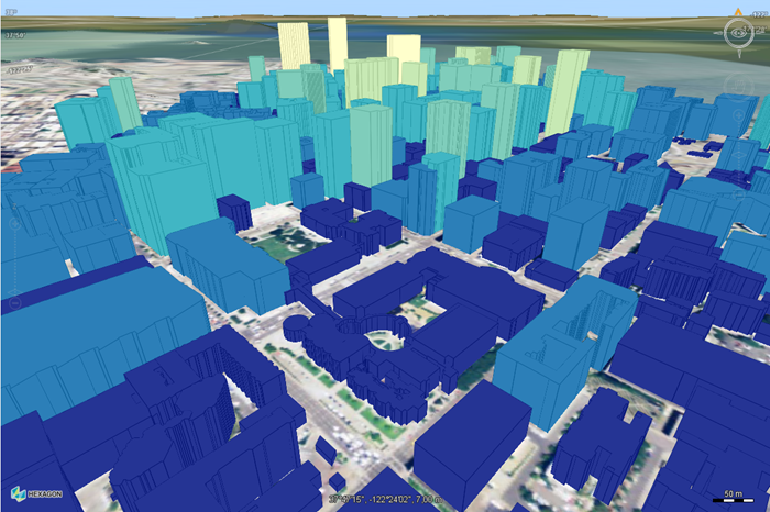
You can also style the extruded shapes according to their height, using a thematic color range. To do so, you can use a Categorize function to define the stroke and fill color. Such a function maps a continuous set of values, such as heights, on a set
of discrete value, such as colors.
This example illustrates the combination of the vendor-specific options to enable extruded shapes and the Categorize function to enable thematic styling based on building heights:
<?xml version='1.0' encoding='UTF-8'?>
<FeatureTypeStyle xmlns="http://www.opengis.net/se"
                  xmlns:ogc="http://www.opengis.net/ogc"
                  xmlns:xsi="http://www.w3.org/2001/XMLSchema-instance"
                  xsi:schemaLocation="http://www.opengis.net/se http://schemas.opengis.net/se/1.1.0/FeatureStyle.xsd     http://www.opengis.net/ogc http://schemas.opengis.net/filter/1.1.0/filter.xsd"
                  version="1.1.0">
  <Rule>
    <PolygonSymbolizer>
      <Fill>
        <SvgParameter name="fill-opacity">
          <ogc:Literal>1.0</ogc:Literal>
        </SvgParameter>
        <SvgParameter name="fill">
          <Categorize threshholdsBelongTo="preceding">
            <LookupValue>
              <ogc:PropertyName>MAXHEIGHT</ogc:PropertyName>
            </LookupValue>
            <Value>#253494</Value>
            <Threshold>50</Threshold>
            <Value>#2c7fb8</Value>
            <Threshold>100</Threshold>
            <Value>#41b6c4</Value>
            <Threshold>150</Threshold>
            <Value>#7fcdbb</Value>
            <Threshold>180</Threshold>
            <Value>#c7e9b4</Value>
            <Threshold>220</Threshold>
            <Value>#ffffcc</Value>
          </Categorize>
        </SvgParameter>
      </Fill>
      <Stroke>
        <SvgParameter name="stroke-width">
          <ogc:Literal>1</ogc:Literal>
        </SvgParameter>
        <SvgParameter name="stroke">
          <Categorize threshholdsBelongTo="preceding">
            <LookupValue>
              <ogc:PropertyName>MAXHEIGHT</ogc:PropertyName>
            </LookupValue>
            <Value>#051474</Value>
            <Threshold>50</Threshold>
            <Value>#0c5f98</Value>
            <Threshold>100</Threshold>
            <Value>#2196a4</Value>
            <Threshold>150</Threshold>
            <Value>#5fad9b</Value>
            <Threshold>180</Threshold>
            <Value>#a7c994</Value>
            <Threshold>220</Threshold>
            <Value>#ddddaa</Value>
          </Categorize>
        </SvgParameter>
        <SvgParameter name="stroke-opacity">
          <ogc:Literal>1.0</ogc:Literal>
        </SvgParameter>
      </Stroke>
      <VendorOption name="extruded-shape-minimum">0</VendorOption>
      <VendorOption name="extruded-shape-maximum">MAXHEIGHT</VendorOption>
      <VendorOption name="extruded-shape-reference">ABOVE_ELLIPSOID</VendorOption>
    </PolygonSymbolizer>
  </Rule>
</FeatureTypeStyle>
This image shows the result of this style, applied to the sample buildings file from the LuciadRIA Extruded Shapes sample:

If you save this style in an .sld file with the same file name as the buildings vector data file and store it in the same folder, Lucy or Lucy Map Centric
pick it up automatically when the data loads.
See Styling data with OGC SLD for more information about using and applying OGC SLD/SE styling.